
Stray radiation multi-scale simulation method of complex spatial optical detection system

A stray radiation, space optics technology, applied in the direction of testing optical performance, etc., can solve problems such as changes in the transmission of radiation light and the influence of optoelectronic systems

Inactive Publication Date: 2015-06-10
HARBIN INST OF TECH
View PDF4 Cites 9 Cited by
  • Summary
  • Abstract
  • Description
  • Claims
  • Application Information

AI Technical Summary

Problems solved by technology

[0010] The purpose of the present invention is to solve the problem that the transmission of radiation light from the radiation source to the detection mechanism will change, which will affect the photoelectric system, and there is currently a lack of methods for detecting the transmission process of stray radiation in the optical detection system

Method used


Image

  • Stray radiation multi-scale simulation method of complex spatial optical detection system
  • Stray radiation multi-scale simulation method of complex spatial optical detection system
  • Stray radiation multi-scale simulation method of complex spatial optical detection system

Examples


specific Embodiment approach 1

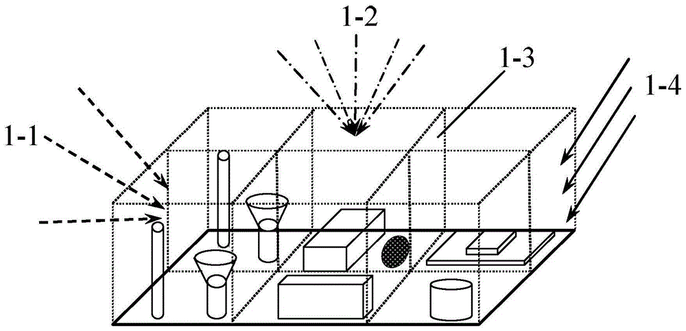
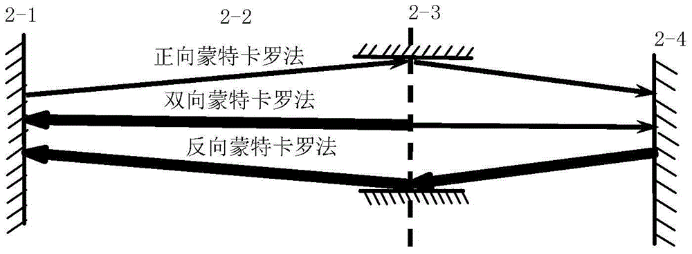
[0025] Specific implementation mode one: refer to figure 1 and Figure 4 Specifically illustrate this embodiment, the stray radiation multi-scale simulation method of complex space optical detection system described in this embodiment, it comprises the following steps:

[0026] Step 1. According to the spatial geometric layout of the opto-mechanical system, the entire space area is surrounded by a virtual boundary covering surface to form a three-dimensional closed space, which is used as the spatial solution area for the propagation of stray radiation, and the radiation characteristics of the virtual boundary covering surface are defined to reflect the characteristics of stray radiation sources,

[0027] Step 2: Use the virtual boundary covering surface to decompose the solution area formed by each device in the optomechanical system into first-level areas, and then divide the first-level area where the external light-shielding structure is located according to the spatial g...

Embodiment

[0044] 1. will attach Figure 4 The entire shading shown in the figure is used as the space solution area. Surface 1 inside the shading is selected as the interface for BDMCM sampling. Reflection is used to track rays in the interval from surface 1 to the stray radiation source, and positive to trace rays.

[0045] 2. Attached Figure 4 Carry out geometric modeling of the shading cover, establish a system coordinate system with the center of the bottom surface as the origin, and carry out mathematical descriptions on the entrance surface 1, the receiving surface 2, the circular table wall surface 3, and the interface 4 in the system coordinate system, and determine the method of each surface line direction.

[0046] 3. Take the honeycomb structure alone as a solution scale, simulate the equivalent scattering characteristics, and establish the equivalent surface scattering model of stray radiation on the inner wall of the hood.

[0047] 4. In order to reduce the amount of ca...

specific Embodiment approach 2

[0048] Embodiment 2: This embodiment is to further explain the multi-scale simulation method of stray radiation in the complex space optical detection system described in Embodiment 1. In this embodiment, in step 3, the virtual interface of each sub-region The optical characteristics are full absorption on one side, directional emission from a black body on the other side or an emission surface within a constrained solid angle.


PUM


Abstract

A stray radiation multi-scale simulation method of a complex spatial optical detection system relates to the field of stray radiation of optical detection systems. The Monte Carlo method of light radiation propagation is used as the basic calculation principle. A modeling is performed under a multi-scale spatial geometric structure and energy levels, so as to perform a simulation calculation to spectral characteristics and energy level information characteristic identifiers. In the calculation process, inter-scale coupling relationships are introduced as bonding points of geometrical characteristics and optical characteristics under different scales. These coupling relationships include regional virtual interface light radiation characteristics, interface energy level division numbers and sampling probability models, and bidirectional reflectance distribution functions of micro-structural stray equivalent surfaces. Then a multilayer domain decomposition technology, a multilevel light division technology, and a reverse / bidirectional Monte Carlo method light tracing technology calculation method are comprehensively utilized for achieving the effective simulation of the multi-scale stray radiation transmission of the spatial optical system. The stray radiation multi-scale simulation method of the complex spatial optical detection system can be applied to the simulation of the multi-scale stray radiation of the optical detection systems.

Description

technical field [0001] The invention relates to a multi-scale stray radiation simulation method, which can be specifically applied in a space optical detection system with a complex structure, and can perform multi-scale analysis on the transmission process of the stray radiation in the complex space optical system. Background technique [0002] In the space detection system, the stray radiation band is divided into visible light and multiple infrared spectral bands (such as short-wave infrared, medium-wave infrared, long-wave infrared, etc.), and the stray radiation from the optical-mechanical system, space background and disturbing environment needs Analysis can only be performed in the same spectral band. Therefore, in the process of analyzing the directional transmission characteristics of stray radiation, it is first necessary to establish an accurate radiation source emission model. [0003] In different spectral bands, the origin, formation mechanism and characterist...

Claims


Application Information

Patent Timeline
IPC IPC(8): G01M11/02
Inventor 夏新林谈和平陈学晁翔宇
Owner HARBIN INST OF TECH
Learn More