
A sheet medium conveying device

A medium conveying and thin sheet technology, which is applied in transportation and packaging, sending objects, thin material processing, etc., can solve the problems of uncertainty, affecting the overall performance of equipment, and increasing the rate of banknote jamming, so as to reduce damage and reduce tearing of banknotes risk, the effect of improving reliability

Active Publication Date: 2017-01-25
GRG INTELLIGENT TECH SOLUTION CO LTD +1
View PDF8 Cites 0 Cited by
  • Summary
  • Abstract
  • Description
  • Claims
  • Application Information

AI Technical Summary

Problems solved by technology

[0003] In the current financial self-service equipment, the conveying mechanism for sheet media such as banknotes is usually realized by pinching flat belts or coiled belts, and banknotes are transported to identification, stacking, storage, etc. Processing is carried out at the corresponding station to realize related functions, such as deposit, banknote withdrawal, temporary storage, circulation processing, etc. In this conveying device, the banknotes are transferred from the flat belt pinch to the roll belt or from the roll belt pinch to the flat belt During the above process, there is a transition area between the flat belt channel and the winding belt channel, and the transition area is realized by a guide plate, which is used to guide the banknotes from one channel to another channel, but the guide plate only serves as a passive guide. There is no pinching device on the channel, so there is uncertainty, especially for some banknotes with a high obsolete rate, the banknote jam rate will increase relatively during the guiding process, which will affect the overall performance of the equipment

Method used


Image

  • A sheet medium conveying device
  • A sheet medium conveying device
  • A sheet medium conveying device

Examples


Embodiment Construction

[0023] In order to further illustrate the sheet medium conveying device provided by the present invention, a further detailed introduction will be made below in conjunction with a diagram of a preferred embodiment of the present invention.

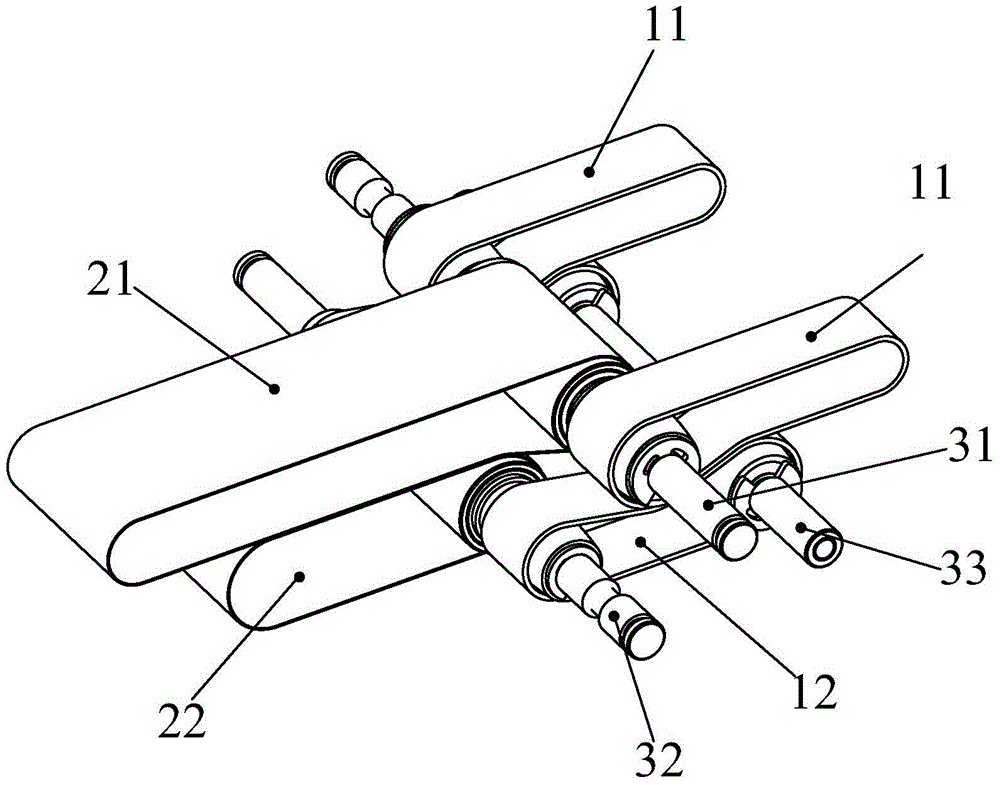
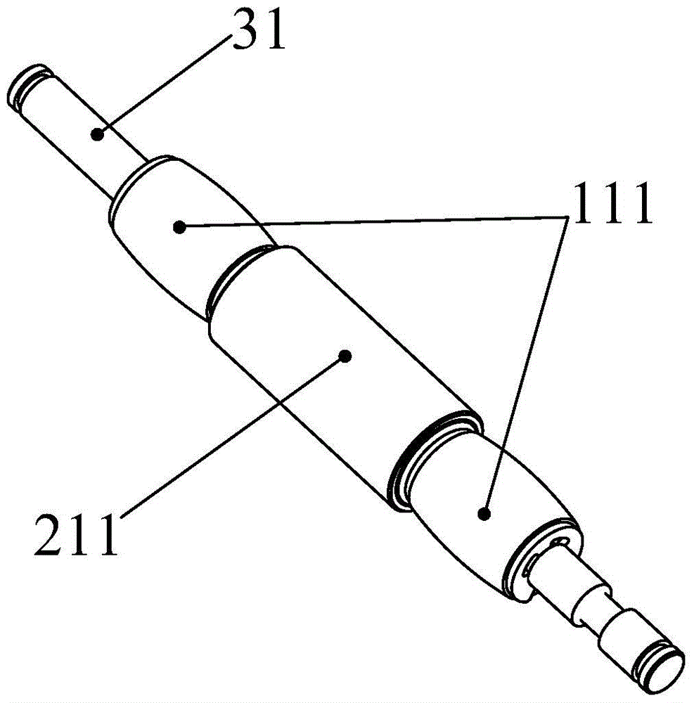
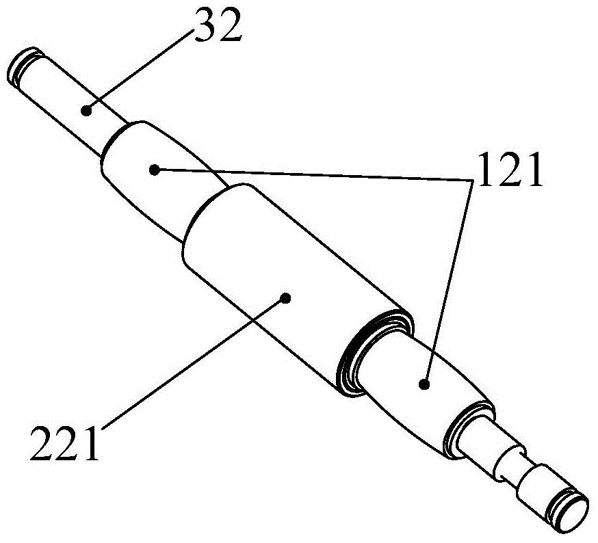
[0024] figure 1 and Figure 5 , is a schematic diagram of a sheet medium conveying device provided by a preferred embodiment of the present invention. The sheet medium conveying device includes a flat belt passage 1, which includes an upper flat belt 11 and a lower flat belt 12 that are assembled in contact with each other. The upper flat belt The belt 11 is supported and driven by at least two upper pulleys 111, and the lower flat belt 12 is supported and driven by at least two lower pulleys 121; a winding channel 2, which includes an upper winding belt 21 and a lower winding belt 22 assembled in contact with each other, The upper winding belt 21 is supported and driven by at least two upper winding wheels 211, and the lower winding belt...


PUM


Abstract

The invention relates to sheet medium transport technology, in particular to a sheet medium conveying device applied to financial equipment for smooth transmission of single paper money. The sheet medium conveying device consisting of flat belts and rolled belts comprises a flat belt passage and a rolled belt passage. The flat belt passage comprises upper flat belts and lower flat belts, the upper flat belts and the lower flat belts are in mutual contact fit, the upper flat belts are supported and driven by at least two upper belt pulleys, and the lower flat belts are supported and driven by at least two lower belt pulleys. The rolled belt passage comprises an upper rolled belt and a lower rolled belt, the upper rolled belt and the lower rolled belt are in mutual contact fit, the upper rolled belt is supported and driven by at least two upper rolled belt pulleys, and the lower rolled belt is supported and driven by at least two lower rolled belt pulleys. Particularly, one of the upper rolled belt pulleys of the upper rolled belt and one of the upper belt pulleys of the upper flat belts are coaxially arranged on a first rotating shaft, and one of the lower rolled belt pulleys of the lower rolled belt and one of the lower belt pulleys of the lower flat belts are coaxially arranged on a second rotating shaft, so that bridging connection between the flat belt passage and the rolled belt passage is realized.

Description

technical field [0001] The invention relates to sheet medium conveying technology, in particular to a sheet medium conveying device composed of a flat belt and a roll belt for smooth transmission of a single banknote in financial equipment. Background technique [0002] In the financial self-service equipment, in order to inspect each piece of sheet media such as banknotes processed in batches one by one, the stacked banknotes need to be separated one by one, and then the separated single banknotes need to be transported, authenticity detected, etc. , in order to ensure the smooth processing of each sheet of medium by the financial self-service equipment, the reliability and stability of the conveying technology for a single sheet of medium are very high. [0003] In the current financial self-service equipment, the conveying mechanism for sheet media such as banknotes is usually realized by pinching flat belts or coiled belts, and banknotes are transported to identification...

Claims


Application Information

Patent Timeline
Patent Type & Authority Patents(China)
IPC IPC(8): B65H29/16B65H29/60
Inventor 周志远
Owner GRG INTELLIGENT TECH SOLUTION CO LTD
Learn More