Fixing device and tensioning element, angle clamping sleeve and fixing method for fixing broken ends of bones in fracture

A fixing device and angle clamping technology, applied in the direction of fixator, internal fixator, internal bone synthesis, etc., can solve the problem that the tensioning element cannot be positioned firmly, and achieve the effect of easy form-locking and reduced body burden.

Active Publication Date: 2017-04-12
HIPP MEDICAL
View PDF2 Cites 0 Cited by
  • Summary
  • Abstract
  • Description
  • Claims
  • Application Information

AI Technical Summary

Problems solved by technology

As in the case of the prior art mentioned above, this appears to be a disadvantage of the tensioning element in question, that is, after the fixation tool is pushed through the adjoining tensioning element and its subsequent insertion into the fracture site Previously, the connected tensioning elements could not be firmly positioned relative to each other

Method used


Image

  • Fixing device and tensioning element, angle clamping sleeve and fixing method for fixing broken ends of bones in fracture
  • Fixing device and tensioning element, angle clamping sleeve and fixing method for fixing broken ends of bones in fracture
  • Fixing device and tensioning element, angle clamping sleeve and fixing method for fixing broken ends of bones in fracture

Examples


Embodiment Construction

[0069] The mode of operation of the fixture 100 is in Figure 8A and 8B Before being described in , individual components will be described first.

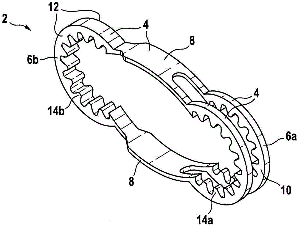
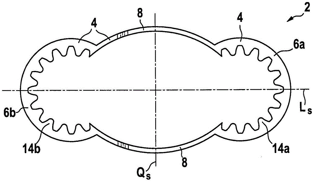
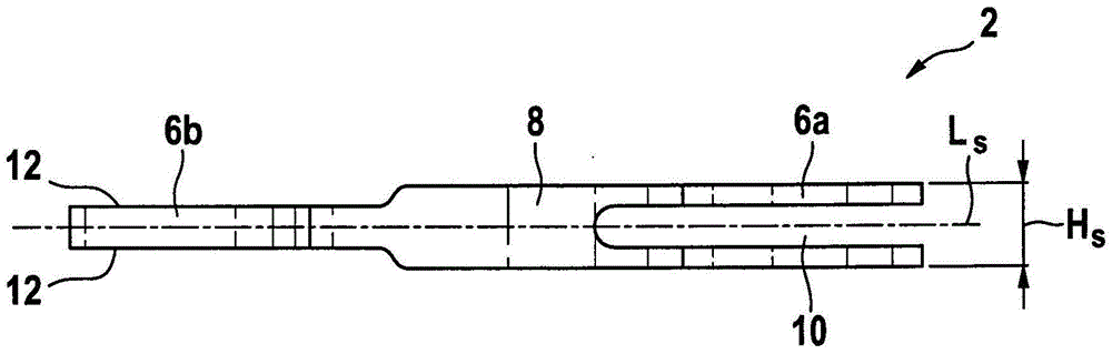
[0070] figure 1 It is a perspective view of the first embodiment of the tensioning element 2 of the present invention, Figure 2A For top view. The tensioning element 2 consists of a corrugated body which is hollow when viewed from above and which has a surrounding wall 4 . The tensioning element 2 furthermore comprises two front-side receiving sections 6 a and 6 b , said 6 a and 6 b facing each other, and two lateral sides with a bow-shaped section 8 . The two front-side receiving sections 6 a and 6 b lie in relation to the transverse axis Q of the tensioning element 2 S face each other and have an outward curvature. The two arcuate sections 8 lie opposite each other with respect to the longitudinal axis LS of the tensioning element 2 and have an outward curvature. figure 1 The tensioning element 2 shown forms a generally ...


PUM


Abstract

Disclosed is a fixation device for fixing the broken ends of bones in fractures, the device having at least two tensioning elements (2a, 2b), each tensioning element having a body that is hollow and corrugated when viewed from above , with a continuous wall (4) and two receiving sections (6a, 6b) facing each other at the end faces. The device also has at least one clamping sleeve and at least two fastening means that can be placed in the end face receiving section. The at least two tensioning elements (2a, 2b) are placed relative to each other such that a receiving section (6a, 6b) of each tensioning element (2a, 2b) is aligned with a corresponding receiving section of the other tensioning element, And the clamping sleeve penetrates both sections, connecting the two tensioning elements (2a, 2b) to each other. According to the invention, the clamping sleeve is moreover an angled clamping sleeve (15) connected to at least two tensioning elements (2a, 2b) such that the latter are positioned at a predetermined angle relative to each other.

Description

technical field [0001] The present invention relates to a fixation device for fixing bone stumps in fractures as claimed in claim 1, as well as to a tensioning element used thereby as claimed in claim 23 and to a tensioning element used thereby as claimed in claim 25. Angle clamping sleeve. The invention also relates to a method for fixing bone stumps in fractures as claimed in claim 27 . Background technique [0002] When the fracture is not adequately immobilized, callus morphology, such as callus-like thickening of the fracture tip from overgrown bone tissue, may occur. In order to avoid such indirect fracture healing by callousing, bone plates are used, which are applied and attached to the outer surface of the broken bone so that the position of the fracture is shaped, eg fixed, during the healing process. [0003] In addition, when compressive forces act on the fracture's seam site, this favorably affects the healing process of the fracture. In this way, a special f...

Claims


Application Information

Patent Timeline
Patent Type & Authority Patents(China)
IPC IPC(8): A61B17/68A61B17/80
CPCA61B17/68A61B17/8004A61B17/8085A61B2017/681A61B17/82
Inventor 马库斯·卫曾格
Owner HIPP MEDICAL
Why Eureka
Try Eureka