
Stroke-controllable circuit breaker

A circuit breaker and stroke technology, applied in the direction of high-voltage air circuit breakers, circuits, electrical components, etc., can solve the problems of changing the moving contact movement stroke, increasing the closing and opening time of the circuit breaker, and failure of opening and closing, and achieve closing and opening. The action is completely consistent, the effect of shortening the closing and opening time, and reducing the degree of wear and tear

Active Publication Date: 2015-04-29
SUZHOU SHIYUAN SPECIAL ELECTRIC
View PDF4 Cites 8 Cited by
  • Summary
  • Abstract
  • Description
  • Claims
  • Application Information

AI Technical Summary

Problems solved by technology

[0002] A circuit breaker is generally composed of an arc extinguishing chamber and a driving mechanism. The driving mechanism drives the moving contact to contact or move away from the static contact through the intermediate transmission mechanism, so as to realize the closing and opening movement of the circuit breaker. The driving mechanism and the transmission mechanism of the circuit breaker Most of them are directly rigidly connected, and the collision between the moving contact and the static contact is violent, which intensifies the wear between the two, causing the movement stroke of the moving contact to change, and the mechanical vibration of the circuit breaker itself and the fatigue of the spring will change the dynamic contact. The stroke of the contact, in the existing public technology, the overtravel of the moving contact of the circuit breaker is not easy to detect and adjust. When the change of the stroke of the moving contact reaches a certain level, it will affect the reliability of the closing and opening of the circuit breaker, resulting in The closing is not in place, the arcing time is too long, and even the contacts are burned
Especially for multi-phase circuit breakers, the action strokes of the moving contacts between the phases are inconsistent, which will cause the dispersion of the closing and opening movement time of each phase of the circuit breaker to be too large, and the closing and opening time is too long, resulting in deterioration of breaking performance or even breaking failure with serious consequences
Furthermore, due to technical defects in the design of the transmission mechanism, the operation synchronization between each phase cannot be guaranteed, which increases the closing and opening time of the circuit breaker.

Method used


Image

  • Stroke-controllable circuit breaker
  • Stroke-controllable circuit breaker
  • Stroke-controllable circuit breaker

Examples


Embodiment Construction

[0021] The present invention will be further described in detail below in conjunction with the accompanying drawings, so that those skilled in the art can implement it with reference to the description.

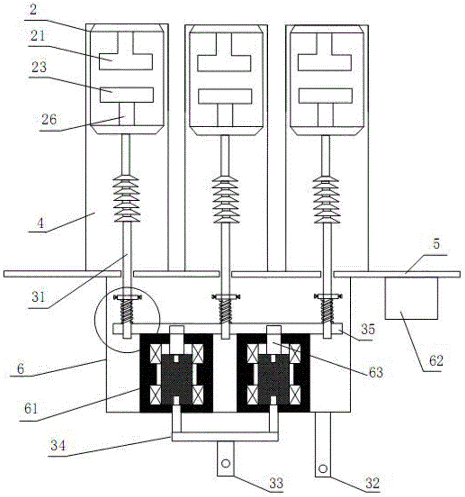
[0022] like Figure 1-3 As shown, a stroke-controllable circuit breaker provided by the present invention includes:

[0023] The arc extinguishing chamber 2, whose arc extinguishing medium can be oil, vacuum or insulating gas, has a static contact 21 built in its upper end, and a movable contact 23 is arranged at a corresponding interval directly below the static contact 21. The lower part of the contact 23 is connected with a pull rod. The pull rod is composed of a moving conductive rod 26 and an insulating pull rod 31. The upper end of the moving conductive rod 26 is connected to the lower end of the moving contact 23, and its lower end is drawn out from the arc extinguishing chamber 2 and connected to the insulating pull rod 31 upper end connection; drive mechanism 61, wh...


PUM


Abstract

The invention discloses a stroke-controllable circuit breaker which comprises an arc extinguish chamber and a driving mechanism, wherein static contacts are arranged inside the upper end of the arc extinguish chamber; moving contacts are correspondingly arranged right below the static contacts at intervals; pull rods are connected with the lower parts of the moving contacts; the driving mechanism is elastically connected with driving rods and used for driving the pull rods to move upwards and downwards, thereby driving the moving contacts to be in contact with or move away from the static contacts. The stroke-controllable circuit breaker has great application values as the abrasion degree of contacts of a circuit breaker is effectively reduced, the closure and opening time of the circuit breaker is shortened and the property of the circuit breaker is improved.

Description

technical field [0001] The invention relates to the field of high-voltage circuit breakers, in particular to a circuit breaker with controllable stroke. Background technique [0002] A circuit breaker is generally composed of an arc extinguishing chamber and a driving mechanism. The driving mechanism drives the moving contact to contact or move away from the static contact through the intermediate transmission mechanism, so as to realize the closing and opening movement of the circuit breaker. The driving mechanism and the transmission mechanism of the circuit breaker Most of them are directly rigidly connected, and the collision between the moving contact and the static contact is violent, which intensifies the wear between the two, causing the movement stroke of the moving contact to change, and the mechanical vibration of the circuit breaker itself and the fatigue of the spring will change the dynamic contact. The stroke of the contact, in the existing public technology, ...

Claims


Application Information

Patent Timeline
IPC IPC(8): H01H33/42H01H33/38H01H33/46H01H33/53
CPCH01H33/38H01H33/42H01H33/46H01H33/53
Inventor 赵甫修
Owner SUZHOU SHIYUAN SPECIAL ELECTRIC
Learn More