Operating mechanism limiting structure based on magnetic suspension technology

A technology of operating mechanism and limit structure, applied in the direction of contact drive mechanism, etc., can solve the problems of increasing hidden safety hazards, large module occupied space, increasing the size of the operating mechanism, etc. Avoid the effect of misuse

Active Publication Date: 2015-04-29
GUANGZHOU BAIYUN ELECTRIC EQUIP
View PDF2 Cites 0 Cited by
  • Summary
  • Abstract
  • Description
  • Claims
  • Application Information

AI Technical Summary

Problems solved by technology

[0007] At present, most of the limit structures used in GIS operating mechanisms only use spring parts combined with complex parts to realize their limit and reset functions. The design and parts are quite complicated, the number of parts is large, the cost is high, and the module takes up space Large, increasing the size of the operating mechanism, and often when the operating mechanism is electrically operated, the parts of the limited structure still act on the rotating parts of the main body, which greatly reduces the mechanical life of the operating mechanism's electric operation and increases potential safety hazards

Method used


Image

  • Operating mechanism limiting structure based on magnetic suspension technology
  • Operating mechanism limiting structure based on magnetic suspension technology
  • Operating mechanism limiting structure based on magnetic suspension technology

Examples


Embodiment Construction

[0057] Further detailed description will be made below in conjunction with accompanying drawing and invention:

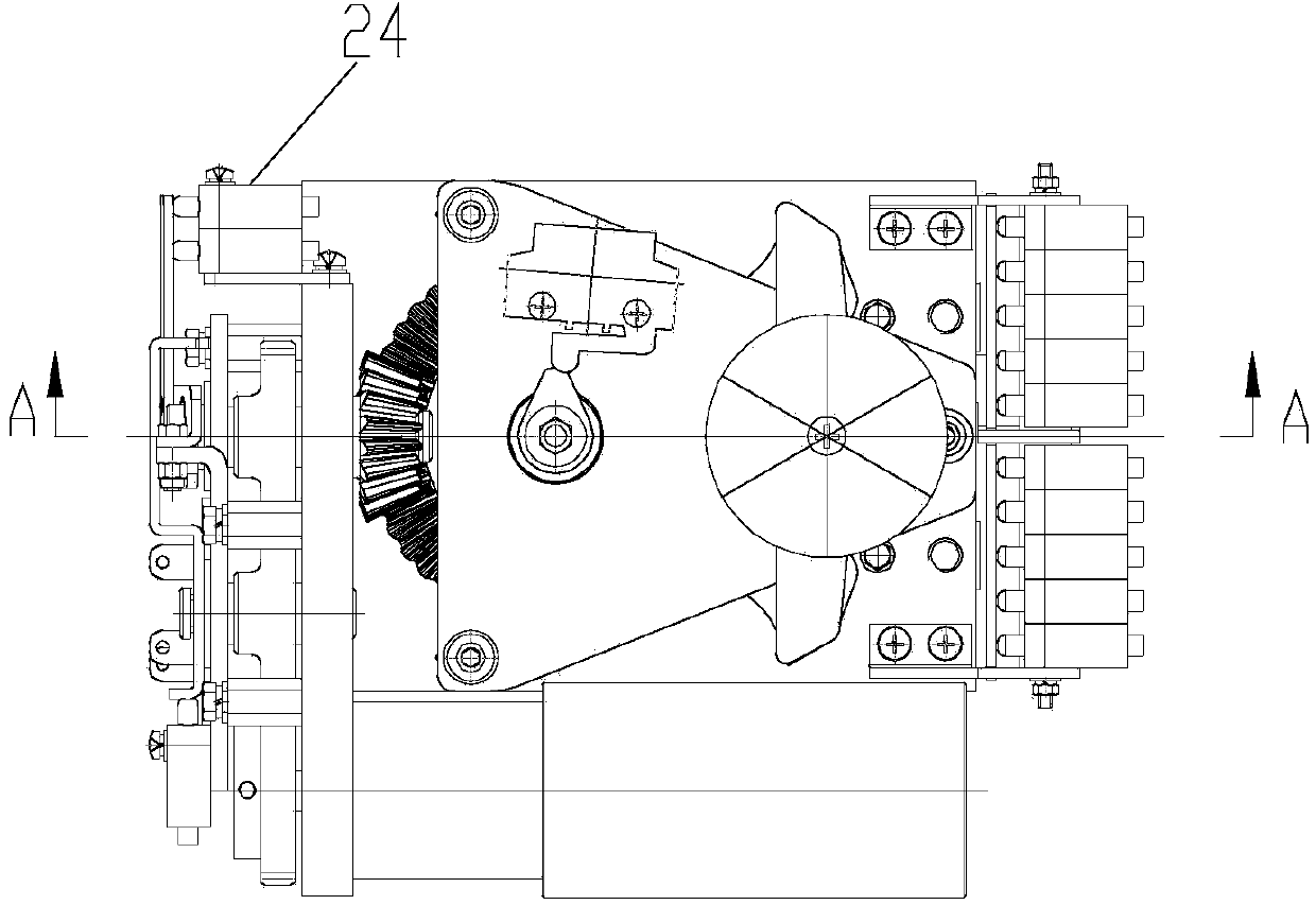
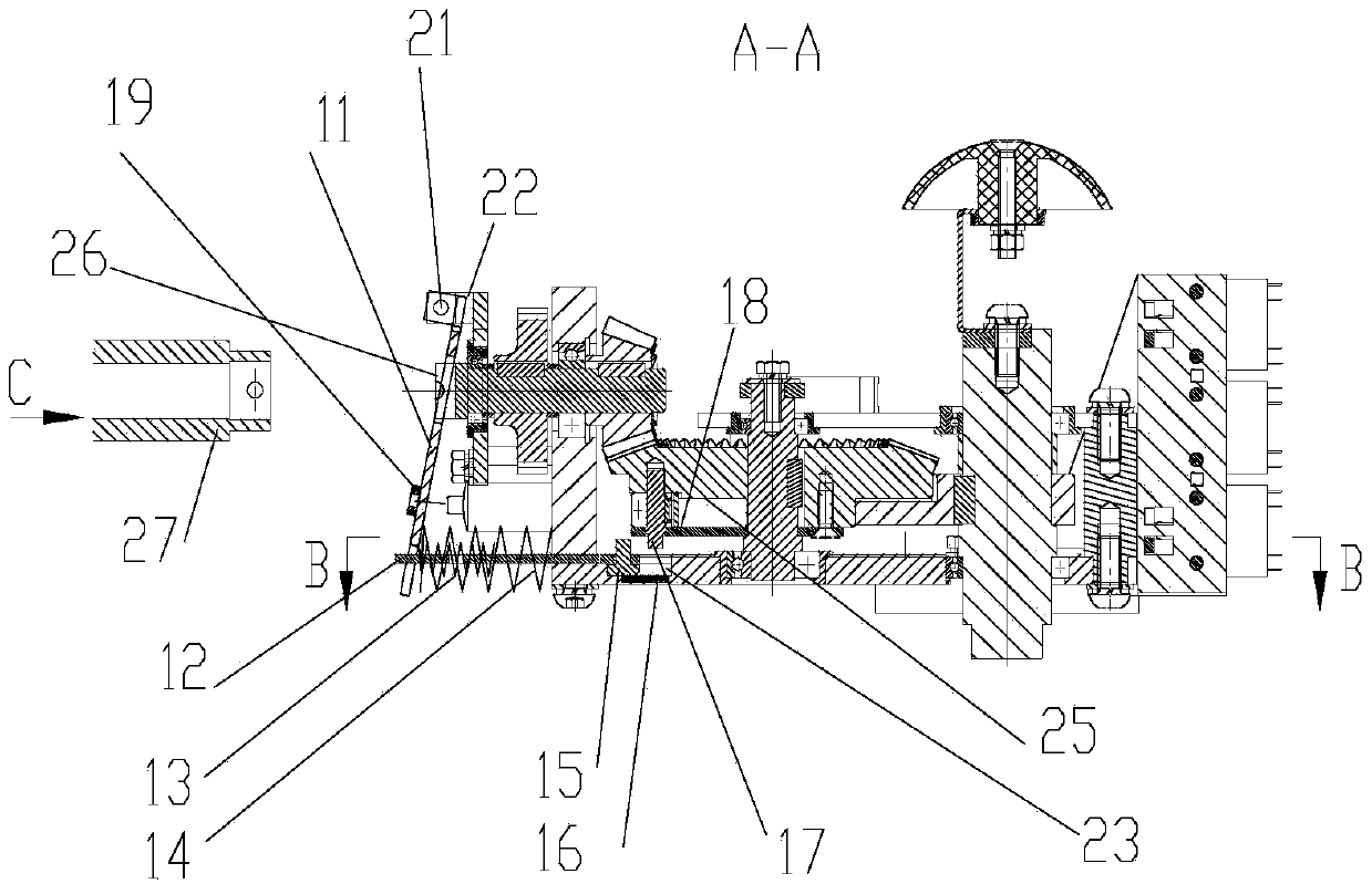
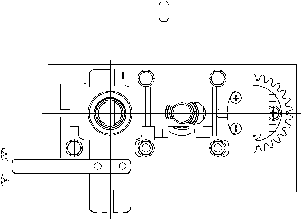
[0058] See Figure 1- Figure 19 , which is an embodiment in which the limit structure based on magnetic suspension technology of the present invention is applied to the GIS three-position switch operating mechanism. The operating mechanism includes a horizontal rotating part and is located in a housing. On the base 23, there are three layers of groove cavities: referring to Fig. 11, the bottom one is a small long rectangular groove or hole 31, in which a guiding permanent magnet 16 of the same shape is fixed; the middle one is a large long rectangular groove 32, one of its long ends is deformed into a triangular groove; the uppermost is a T-shaped groove 33, and its long end extends to the side of the base 23; the long axes of the three grooves coincide; The stop block 15 corresponds to the three-layer groove cavity when turning.

[0059] Also included are:

[0060...


PUM


Abstract

Disclosed is an operating mechanism limiting structure based on the magnetic suspension technology. An operating mechanism is provided with a rotating part and located inside a shell. Three layers of groove cavities are formed in a base or shell base plate (23) below the horizontal rotating part. A small rectangular groove or hole (31) is formed in the bottommost layer, and a guiding permanent magnet (16) in the same shape as the small rectangular groove is fixedly arranged inside the small rectangular groove. A large rectangular groove (32) is formed in the middle layer, and the long end of the large rectangular groove deforms to form the triangular groove. A T-shaped groove (33) is formed in the upmost layer, and the long end of the T-shaped groove extends to the edge of the base (23). The long axes of the three grooves coincide. A downward-protruding sliding stop block (15) is fixedly arranged on the bottom face of the horizontal rotating part and corresponds to the three layers of groove cavities when rotating. The operating mechanism limiting structure further comprises a sliding plate (12), the sliding stop block (15) and a rotating pressing plate (11). According to the operating mechanism limiting structure based on the magnetic suspension technology, and particularly the GIS three-station switch operating mechanism limiting structure based on the magnetic suspension technology, the design is more flexible and simpler, the structure is compact, the occupied space is small, and the cost is low.

Description

technical field [0001] The invention relates to a position-limiting structure of an operating mechanism based on magnetic suspension technology, in particular to a position-limiting structure of a GIS three-position switch operating mechanism based on magnetic suspension technology. Background technique [0002] Many devices all use limit structures, and most of the existing limit structures only use spring parts combined with complex parts combinations to realize their limit and reset functions. [0003] The invention proposes a position limiting structure of an operating mechanism based on magnetic suspension technology, and in particular relates to a position limiting structure of a GIS three-position switch operating mechanism based on magnetic suspension technology. [0004] The so-called GIS refers to the gas-insulated metal-enclosed switchgear, and the three-station refers to the three working positions of the switchgear: 1. The position where the main breakout of the...

Claims


Application Information

Patent Timeline
IPC IPC(8): H01H3/32
CPCH01H3/32
Inventor 范坤文伍兆辉邓国锐
Owner GUANGZHOU BAIYUN ELECTRIC EQUIP
Why Eureka
Try Eureka