
Rotating motor

A technology for rotating electrical machines and rotating shafts, applied to electrical components, electromechanical devices, electrical components, etc., can solve the problem of inability to cool the rotor 72, and achieve the effect of suppressing insufficient supply and reducing supply pressure

Active Publication Date: 2015-04-15
HONDA MOTOR CO LTD
View PDF10 Cites 3 Cited by
  • Summary
  • Abstract
  • Description
  • Claims
  • Application Information

AI Technical Summary

Problems solved by technology

Therefore, the rotor 72 may not be sufficiently cooled

Method used


Image

  • Rotating motor
  • Rotating motor
  • Rotating motor

Examples


no. 1 approach

[0077] 1. Description of the overall structure

[0078] [1-1. Overall structure]

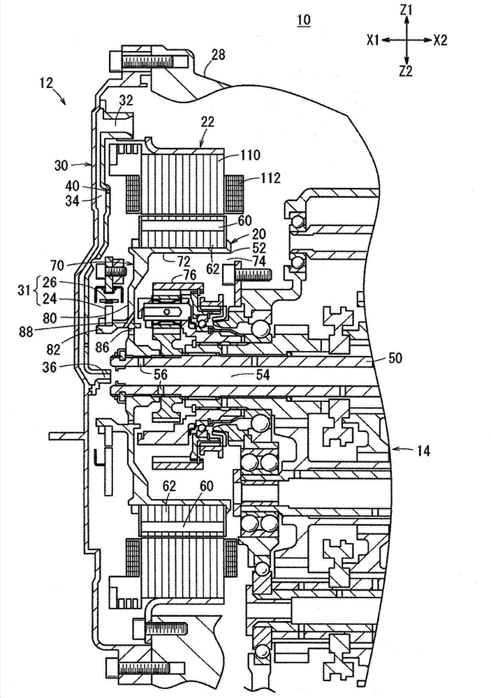
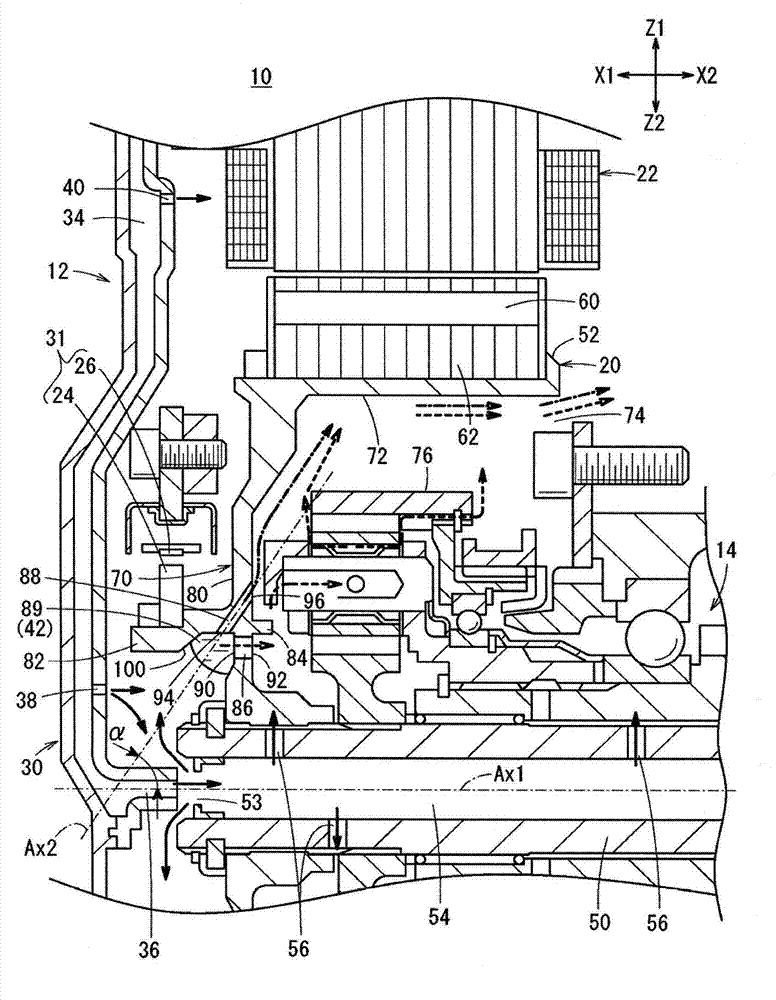
[0079] figure 1 It is a partial cross-sectional view showing a vehicle 10 mounted with a motor 12 as a rotating electric machine according to the first embodiment of the present invention focusing on a cooling system (refrigerant supply mechanism). figure 2 It is a partially enlarged cross-sectional view showing the flow of the cooling oil 42 in the motor 12 of the first embodiment. exist figure 2 In , thick arrows of solid lines, dashed lines, and one-dot chain lines (however, except for the lead-out lines for reference symbols) indicate the flow of the cooling oil 42 . That is, the arrows of the solid line indicate the flow of the cooling oil 42 supplied from the side cover 30 (described later) and the flow of the cooling oil 42 supplied into the rotating shaft 50 . The dotted arrows indicate the flow of the cooling oil 42 passing through or after passing through the first through holes...

no. 2 approach

[0149] 1. Explanation of overall structure (differences from the first embodiment)

[0150] In the second embodiment, the shape of the cylindrical member 52a is different from that of the cylindrical member 52 of the first embodiment. Components that are the same as those in the first embodiment are denoted by the same reference numerals and description thereof will be omitted.

[0151] Figure 14 It is a partial enlarged cross-sectional view showing the flow of the cooling oil 42 in the motor 12a of the second embodiment. exist Figure 14 In , arrows of solid lines, dashed lines, and one-dot chain lines (however, the lead-out lines for reference symbols are excluded.) indicate the flow of the cooling oil 42 . That is, the arrows of the solid line indicate the flow of the cooling oil 42 supplied from the side cover 30 and the flow of the cooling oil 42 supplied into the rotating shaft 50 . The dotted arrows indicate the flow of the cooling oil 42 passing through or after p...


PUM


Abstract

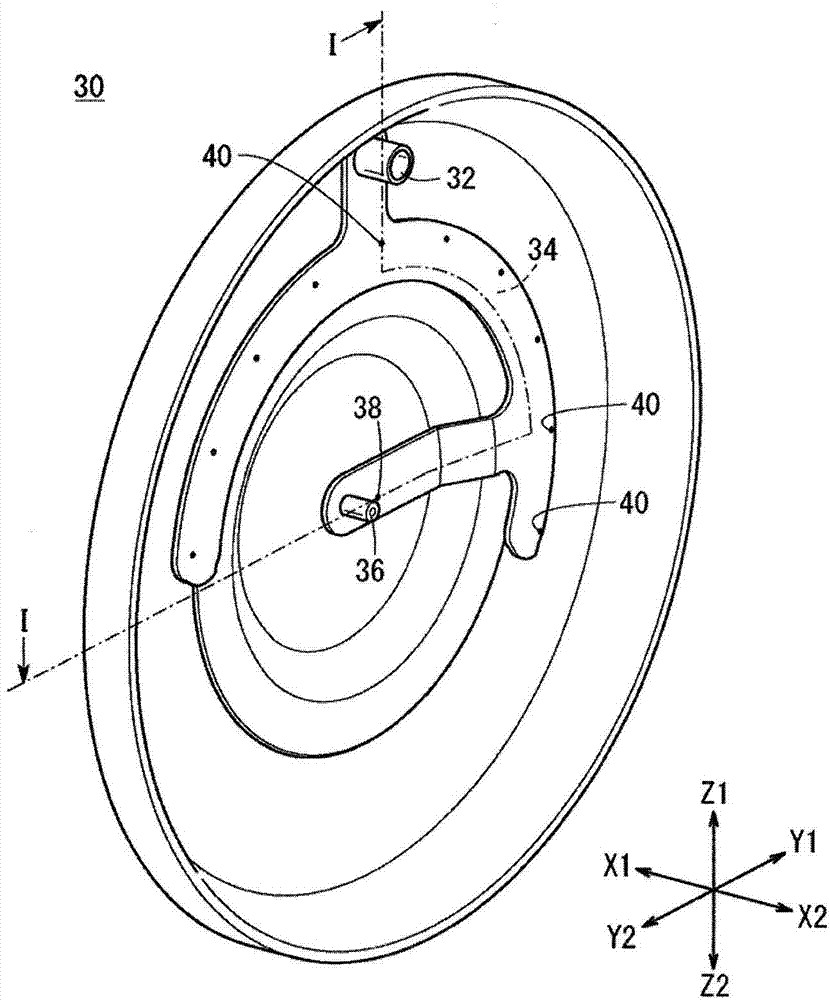
The invention provides a rotating motor capable of cooling the inside properly. A refrigerant supply mechanism (30) of the rotating motor (12) supplies cooling fluid (42) from a position of one end side closer to a rotating shaft than a bottom surface of a cylindrical member (52) to the bottom surface (70). The bottom surface (70) has a first through hole (86) and a second through hole (88) which axially run through along the rotating shaft (50), and the cooling fluid (42) is supplied into the cylindrical member (52) through the first through hole (86) and the second through hole (88). On the inner side of the cylindrical member (52), an outlet side opening part (92) of the first through hole (86) is formed in a position closer to a radial outer side than the rotating shaft (50), and an outlet side opening part (96) of the second through hole (88) is formed in a position closer to a radial outer side than the outlet side opening part (92) of the first through hole (86).

Description

technical field [0001] The present invention relates to a rotating electrical machine capable of properly cooling the inside. Background technique [0002] Patent Document 1 discloses a plurality of structures for cooling a motor ( Figure 1 to Figure 11 ). Among these structures, there is a structure in which the cooling oil is circulated through the inside of the shaft 28 as a structure in which the cooling oil is supplied from the inner side of the motor toward the radially outer side ( Figure 7 and Figure 8 ). [0003] Patent Document 2 discloses a structure in which lubricating oil as cooling oil is supplied from the inside toward the radially outside of the electric motor 7 . Specifically, in Patent Document 2, the lubricating oil sprayed from the oil supply hole 11b of the first main shaft 11 is placed on the inside of the rotor 72 (that is, inside the fixing portion 72c that fixes the rotor yoke 72b ). The planetary gear mechanism 30 of the transmission 20 supp...

Claims


Application Information

Patent Timeline
IPC IPC(8): H02K9/19
CPCH02K9/193
Inventor 吉田秀幸大矢聪义
Owner HONDA MOTOR CO LTD
Learn More