Stochastic rasterization of waveform trace displays

A random incremental, waveform monitor technology, applied in the field of waveform instruments

Inactive Publication Date: 2015-04-15
TEKTRONIX INC
View PDF5 Cites 2 Cited by
  • Summary
  • Abstract
  • Description
  • Claims
  • Application Information

AI Technical Summary

Problems solved by technology

Then increment the currently stored value based on the percentage for the specified range

Method used


Image

  • Stochastic rasterization of waveform trace displays
  • Stochastic rasterization of waveform trace displays
  • Stochastic rasterization of waveform trace displays

Examples


Embodiment Construction

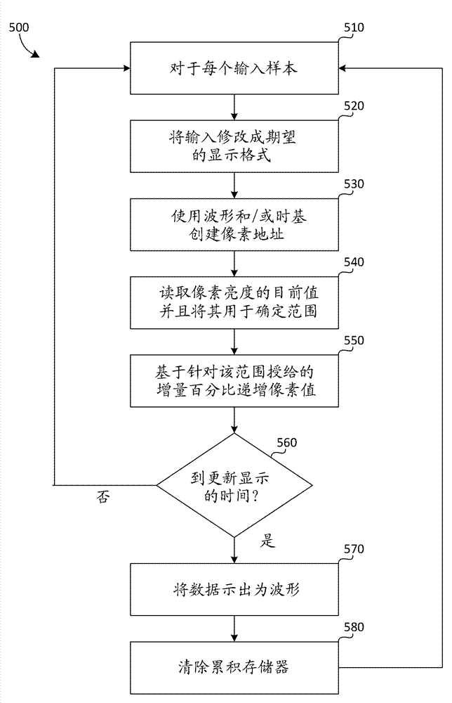
[0016] figure 1 is a functional block diagram of a conventional waveform monitor 100. The input signal is processed by the computing section 170 to create various display modes. The outputs of the computing section 170 and the timing signal generating circuit 110 are inputs to the address generator 130 . The address generator 130 generates address signals for pixels of the image memory 140 . In operation, a waveform signal is received at an input and data is generated from the waveform signal, and for each address generated by address generator 130 a time base is stored in image memory 140 . Data may be accumulated for several input cycles before the contents of memory 140 are transferred for display on display unit 120, for example during a vertical sync period. The memory 140 is then reset and the accumulation cycle begins again. Some waveform monitors may include two memories such that one memory is accumulated while the second memory is formatted for display. The meth...


PUM


Abstract

A stochastic system in a waveform monitor reduces the amount of memory used to store waveform data as it is being accumulated. The system produces a high quality trace display using fewer bits of memory by incrementing pixels using stochastic methods. In at least some embodiments, possible memory values are divided into two or more value ranges and an increment percentage is ascribed for each of the value ranges. During operation, first a present stored value is read from the memory store and its ascribed increment percentage for the particular range is selected. Then the present stored value is stochastically incremented based on the percentage for the particular range.

Description

[0001] Cross References to Related Applications [0002] This application claims priority to US Provisional Application 61 / 887,554, filed October 7, 2013, entitled STOCHASTIC RASTERIZATION OF WAVEFORM TRACE DISPLAYS, the contents of which are hereby incorporated by reference in their entirety. technical field [0003] The present disclosure relates to waveform instruments, and more particularly, to methods of randomly incrementing stored values ​​in waveform instruments. Background technique [0004] Waveform monitors generate images of waveforms to allow technicians to visualize circuit activity. They are typically used to measure video signals, but can also measure other types of signals. [0005] Current waveform monitors use external memory to store the data used to generate waveform traces. The data forming the waveform on the pixelated display is incremented in the external memory each time the memory location associated with the pixel is accessed. After the increme...

Claims


Application Information

Patent Timeline
Patent Type & Authority Applications(China)
IPC IPC(8): G01R13/00
CPCG01R13/0227G06T11/206
Inventor J.哈巴德M.S.奥弗顿
Owner TEKTRONIX INC
Why Eureka
Try Eureka