Grid polarizing element and manufacturing method of grid polarizing element

A technology for component manufacturing and grid polarization, applied in the field of polarizing components, can solve problems such as the decrease in extinction ratio, and achieve the effects of improved uniformity and easy microfabrication

Active Publication Date: 2018-04-13
USHIO DENKI KK
View PDF5 Cites 0 Cited by
  • Summary
  • Abstract
  • Description
  • Claims
  • Application Information

AI Technical Summary

Problems solved by technology

Therefore, in the past, it was difficult to use polarizing elements to polarize light from the short-wavelength range of the visible to the ultraviolet region, but with the advancement of microfabrication technology (lithography technology) in recent years, practical use has become completely possible
[0012] However, the inventors found the problem that when a grid polarizing element of a certain size is manufactured and polarized light is irradiated to a certain size area, the extinction ratio ER decreases in the peripheral portion of the irradiated area.

Method used


Image

  • Grid polarizing element and manufacturing method of grid polarizing element
  • Grid polarizing element and manufacturing method of grid polarizing element
  • Grid polarizing element and manufacturing method of grid polarizing element

Examples


Embodiment 1

[0101] Next, examples belonging to the above-mentioned embodiments will be described.

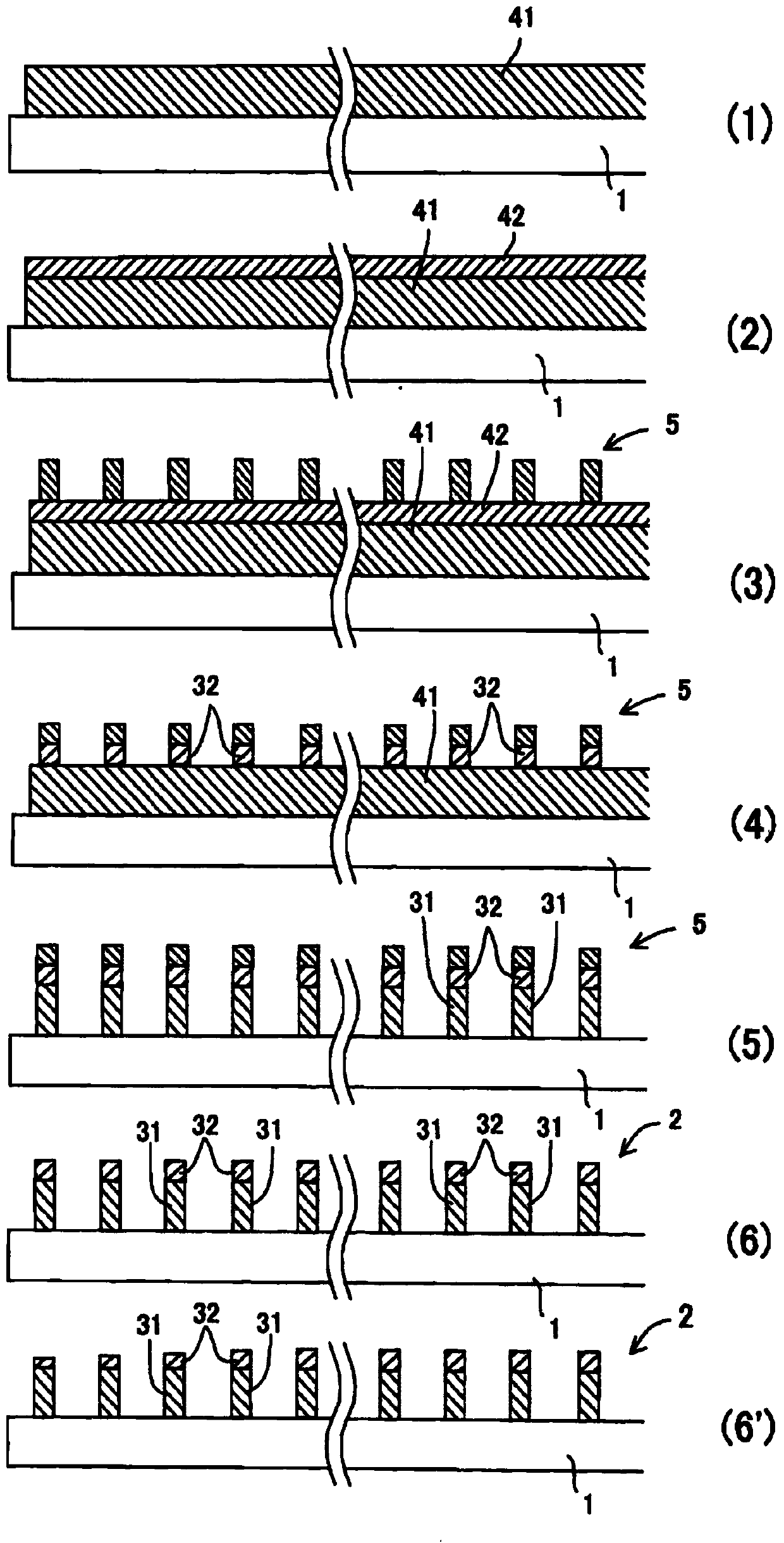
[0102] In the method for manufacturing a grid polarizing element in the embodiment, a silicon film having a thickness of 100 nm is formed as a first thin film on a transparent substrate made of synthetic quartz by a magnetron sputtering device. At this time, the temperature of the stage on which the transparent substrate was placed was room temperature, and argon gas was introduced into the chamber at a flow rate of 30 sccm as a process gas. In this state, a high frequency of 13.56 MHz was applied at 300 W to silicon as a target.

[0103] Argon gas is decomposed by the above-mentioned high frequency into a plasma state, and argon ions are generated. The generated argon ions collide with the negative potential silicon target while being accelerated, and knock out silicon from the target. The knocked-out silicon is deposited on a transparent substrate arranged to face the target to form a f...


PUM

PropertyMeasurementUnit
heightaaaaaaaaaa
heightaaaaaaaaaa
wavelengthaaaaaaaaaa

Abstract

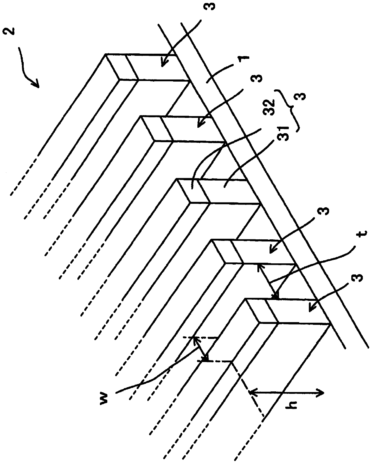
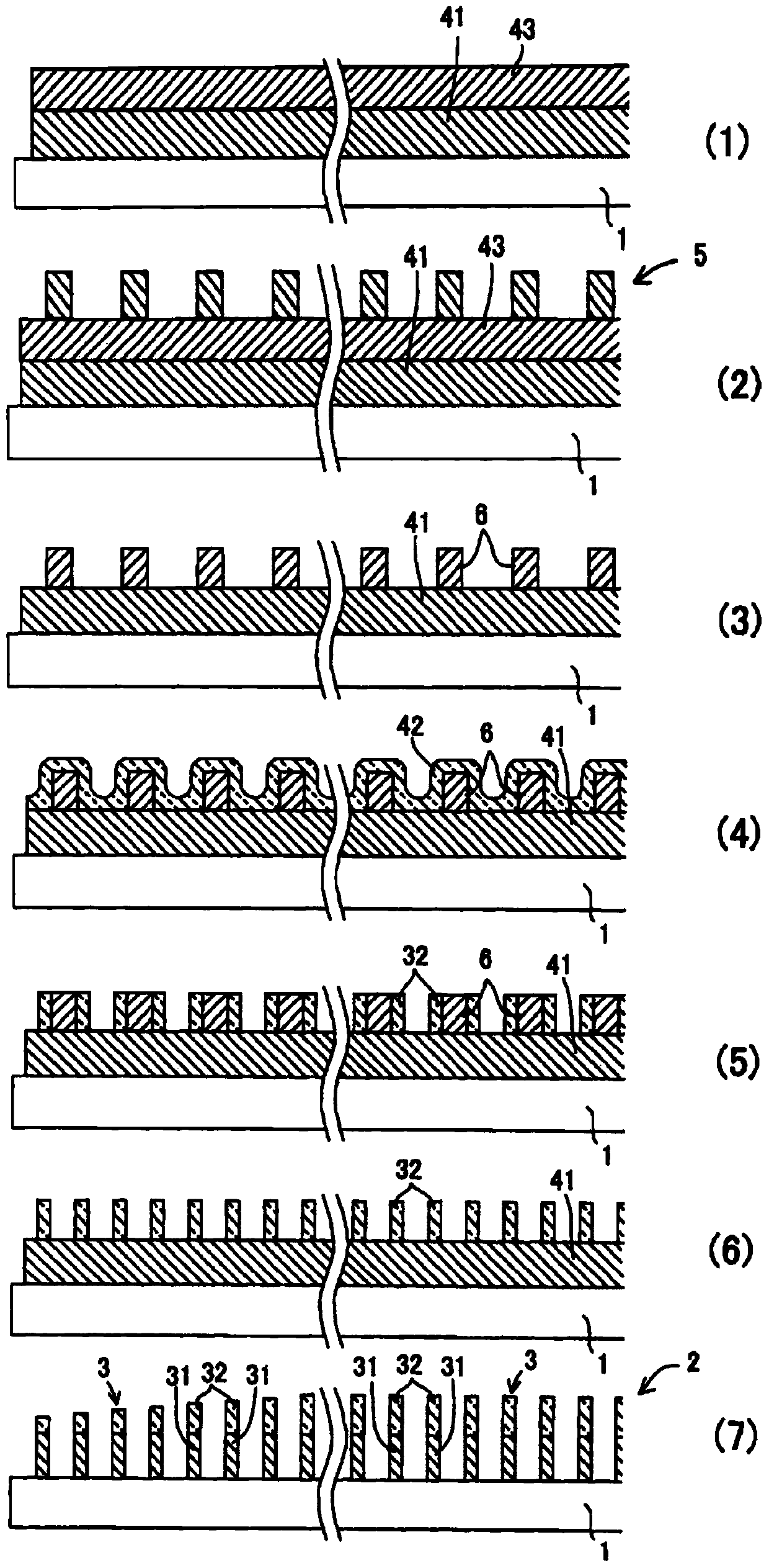
A grid polarization device which can maintain an extinction ratio in a peripheral part is provided. Each linear unit (3) which comprises a line-shaped grid (2) which is installed on a transparent substrate (1) includes: a first layer (31) which polarizes light and a second layer (32) which is located in a light input part of the first layer (31). The second layer (32) is formed with a transmissive material, has a height lower than the height of the first layer (31) and is formed with a material which is more resistant to etchant which is used when forming the first layer (31).

Description

technical field [0001] The present invention relates to a polarizing element for obtaining light in a polarized state (polarized light), and more particularly to a grid polarizing element having a grid structure formed on a transparent substrate. Background technique [0002] As polarizing elements for obtaining polarized light, various optical elements such as polarizing filters and polarizing films are known, including portable products such as polarized sunglasses, and polarizing elements are also used in display devices such as liquid crystal displays. Polarizers are classified into several types according to how polarized light is taken out, and one of them is a wire grid polarizer. [0003] The wire grid polarizer has a structure in which a fine striped grid made of metal such as aluminum is provided on a transparent substrate. The separation interval (grid interval) of each linear portion constituting the grid is set to be equal to or less than the wavelength of ligh...

Claims


Application Information

Patent Timeline
Patent Type & Authority Patents(China)
IPC IPC(8): G02B5/30
CPCG02B5/3033G02B5/3041G02B5/3075C08J5/18G02B5/1857G02B5/3058G02F1/133528G02F1/133548
Inventor 鹤冈和之
Owner USHIO DENKI KK
Why Eureka
Try Eureka