
Wiring method

A wiring method, clockwise technology, applied in special data processing applications, instruments, electrical digital data processing, etc., can solve problems such as signal interference, poor peripheral signals, and complicated lines

Inactive Publication Date: 2015-03-18
INVENTEC PUDONG TECH CORPOARTION +1
View PDF1 Cites 0 Cited by
  • Summary
  • Abstract
  • Description
  • Claims
  • Application Information

AI Technical Summary

Problems solved by technology

However, since the more electronic components on the printed circuit board, the more complex the circuits connecting these electronic components will be. Therefore, if two circuits cross, they can only be passed through by means of jumpers or through holes. way of wiring
In this way, not only will the quality of the signal transmission of the line itself be degraded, but it will also have a bad influence on the surrounding signals, such as signal interference, etc.

Method used


Image

  • Wiring method
  • Wiring method
  • Wiring method

Examples


Embodiment Construction

[0032] Below in conjunction with accompanying drawing, structural principle and working principle of the present invention are specifically described:

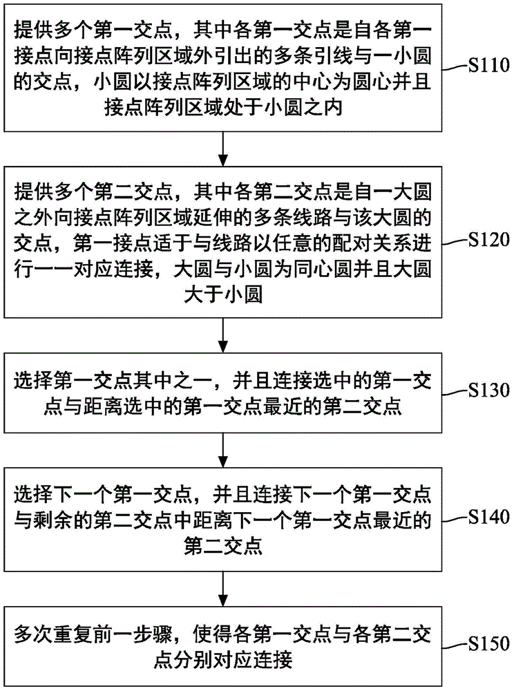
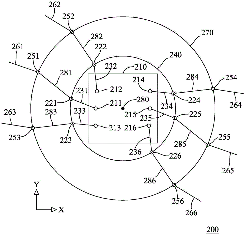
[0033] Please refer to figure 1 , figure 2 As shown, it is a flowchart of the wiring method of the present invention and an implementation example of a printed circuit pattern. The wiring method of this embodiment can be applied to the design of the printed circuit pattern 200, for example. Moreover, the printed circuit pattern 200 has a contact array area 210 corresponding to a Ball Grid Array (BGA), and the contact array area 210 has a plurality of first contacts 211 , 212 , 213 , 214 , 215 , 216 . Among them, the first contacts 211, 212, 213, 214, 215, and 216 correspond to several similar pins of the ball gate package array, and these pins have the same performance and can be interchanged, that is, these pins are not suitable for ball gate package arrays. It is the same for a connection line, suitable for optional one ...


PUM


Abstract

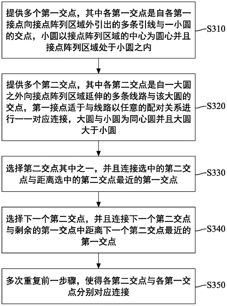
The invention relates to a wiring method. The wiring method is applied to a printed circuit pattern, wherein the printed circuit pattern is provided with a contact array area which comprises a plurality of first contacts. The wiring method comprises the following steps: providing a plurality of first intersecting points, wherein each first intersecting point is the point of intersection of a lead from a corresponding first intersecting point and a small circle, and the contact array area is located in the small circle; providing a plurality of second intersecting points, wherein each second intersecting point is the point of intersection of a line extending towards the contact array area from the outside of a big circle and the big circle, the big circle and the small circle are concentric circles, and the big circle is bigger than the small circle; selecting one of the first intersecting points, and connecting the selected first intersecting point and the corresponding second intersecting point which is closest to the selected first intersecting point; selecting the next first intersecting point, and connecting the selected first intersecting point and the corresponding second intersecting point, which is closest to the selected first intersecting point, in the remaining second intersecting points, so as to enable all the first intersecting points and all the second intersecting points to be connected.

Description

technical field [0001] The invention relates to a wiring method, in particular to a wiring method applied to the design of printed circuit patterns. Background technique [0002] Generally speaking, the production of printed circuit boards (Printed Circuit Board, PCB) usually first conducts circuit layout (Layout) to generate layout drawings. Moreover, as the level of integration is getting higher and higher, most of the current electronic components are packaged together, especially of the same type, so that more electronic components can be configured on the printed circuit board. For example, several resistors are packaged together in parallel, several capacitors are packaged together in parallel, many switches are packaged in parallel, and a large number of complex programmable logic devices (Complex Programmable Logic Device, CPLD) input / output (I / O) interface packaging together. [0003] In order for these electronic components to work with each other, layout enginee...

Claims


Application Information

Patent Timeline
IPC IPC(8): G06F17/50
Inventor 梁磊
Owner INVENTEC PUDONG TECH CORPOARTION
Learn More