
Air duct for locomotive resistance braking device

A resistance braking and air guide technology, applied in the field of air guide, can solve the problem of excessive radiated noise of locomotives and other problems, and achieve the effect of reducing the noise index

Inactive Publication Date: 2015-03-04
CRRC ZIYANG CO LTD
View PDF7 Cites 0 Cited by
  • Summary
  • Abstract
  • Description
  • Claims
  • Application Information

AI Technical Summary

Problems solved by technology

[0004] The purpose of the present invention is to provide an air duct for a locomotive resistance braking device, which solves the technical problem that the radiation noise of an existing locomotive exceeds the standard

Method used


Image

  • Air duct for locomotive resistance braking device

Examples


Embodiment Construction

[0014] The present invention will be further described below in combination with specific embodiments and accompanying drawings.

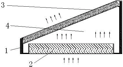
[0015] see figure 1 As shown in the figure, an air guide tube for a locomotive resistance braking device includes a cylinder body 1 with openings at both ends, an air inlet grid 2 is installed at one end of the cylinder body 1, and an air outlet grid 3 is installed at the other end. An oscillation cavity 4 is formed in the cylinder between 1 and the air outlet grid 3 . The shape and size of the vibration cavity 4 are determined according to the profile of the locomotive and the frequency of noise.

[0016] In order to enhance the heat insulation performance, the cylinder 1 is a heat insulation cylinder.

[0017] When in use, the air guide tube is installed at the air inlet and outlet of the locomotive resistance braking device. The high-speed air flow of the resistance braking enters the shock chamber 4 from the air inlet grille 2, and the air fl...


PUM


Abstract

The invention discloses an air duct for a locomotive resistance braking device. The air duct comprises a duct body of which the two ends are open; an air inlet grid is mounted at one end of the duct body, while an air outlet grid is mounted at the other end; an oscillating cavity is formed in the duct body between the air inlet grid and the air outlet grid. The air duct for the locomotive resistance braking device is capable of reducing the index of noise generated by the resistance braking device by more than 10dB (A).

Description

technical field [0001] The invention relates to an air guide tube, in particular to an air guide tube used for a locomotive resistance braking device. Background technique [0002] Compared with locomotives without resistance braking devices, locomotives equipped with resistance braking devices have larger radiated noise values. The reason is that the resistance braking devices themselves generate mechanical, electromagnetic, and high-speed gas flow noise effects result. [0003] How to solve this technical problem has become an urgent problem for those skilled in the art. Contents of the invention [0004] The purpose of the present invention is to provide an air guide tube for a locomotive resistance braking device, which solves the technical problem of excessive radiation noise of an existing locomotive. [0005] The purpose of the present invention is achieved through the following technical solutions: [0006] An air guide cylinder used for a locomotive resistance ...

Claims


Application Information

Patent Timeline
Patent Type & Authority Applications(China)
IPC IPC(8): B60L7/02B61H11/00
Inventor 黎焕先张志刚陈传彬卓文俊江太宏
Owner CRRC ZIYANG CO LTD
Learn More