Electronic equipment
A technology for electronic equipment and ontology, applied in the electronic field, can solve the problems of projection angle and projection bearing surface limitation, and achieve the effect of convenient viewing and user experience.
- Summary
- Abstract
- Description
- Claims
- Application Information
AI Technical Summary
Problems solved by technology
Method used
Image

Examples
no. 1 approach
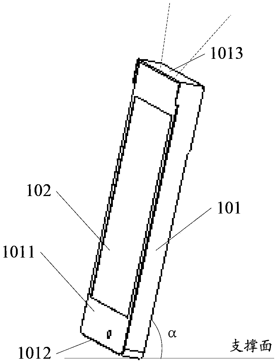
[0044] In the first embodiment, the projection unit 103 is fixedly installed in the main body 101, and when the light output direction of the projection unit 103 faces the fourth surface 1013 opposite to the second surface 1012, the projected light path of the projection unit 103 passes through the fourth surface 1013 on the fourth surface 1013. The second light channel is used to project the second display content on the first bearing surface, such as the ceiling, such as Figure 3a shown.
no. 2 approach
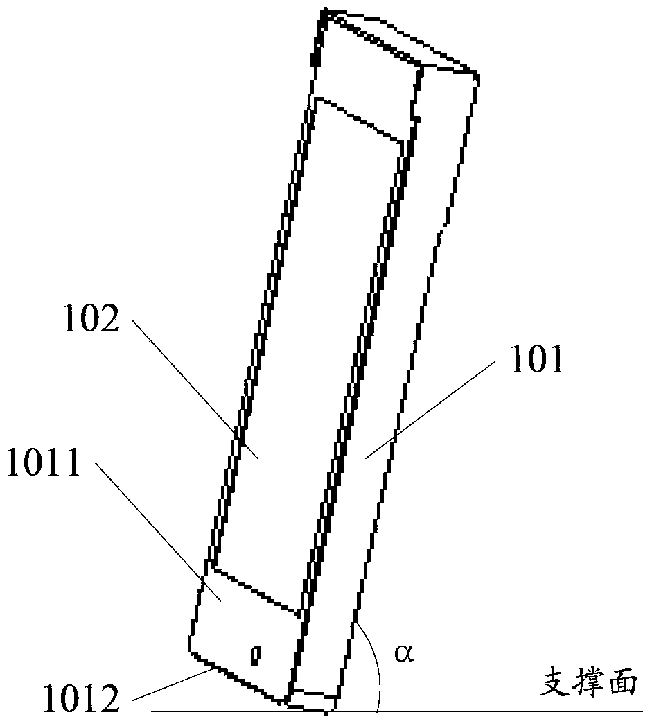
[0045] In the second embodiment, the body further includes a third surface, the third surface is the surface opposite to the first surface 1011; wherein, a first end is formed on the first surface 1011 or the third surface away from the second surface 1012. A light channel. The light path of the projection unit 103 passes through the first light channel to project the second display content on the supporting surface. Such as Figure 3b As shown, the projection unit 103 is fixedly arranged in the main body 101, and the projection light path of the projection unit 103 passes through the first light channel on the first surface 1011 or the third surface to project the second display content on the supporting surface.
no. 3 approach
[0046] The third embodiment, in this embodiment, the projection unit 103 is fixedly installed in the main body 101, and the light emitting direction of the projection unit 103 faces the fourth surface 1013 opposite to the second surface 1012, and the second display content needs to be displayed from the first The light channel is projected on the support surface, so in this embodiment, the electronic device further includes: a first light path changing unit, arranged between the projection unit 103 and the fourth surface 1013, the first light path changing unit and the fourth surface The positional relationship between 1013 has a first relative position and a second relative position. When in the first relative position, it is used to change the optical path of the projection unit 103 so that the optical path passes through the first optical channel.
[0047] In an embodiment, the first optical path changing unit specifically includes a reflector, a rotating member, and the rot...
PUM
 Abstract
Description
Claims
Application Information
 - R&D
- Intellectual Property
- Life Sciences
- Materials
- Tech Scout
- Unparalleled Data Quality
- Higher Quality Content
- 60% Fewer Hallucinations
Browse by: Latest US Patents, China's latest patents, Technical Efficacy Thesaurus, Application Domain, Technology Topic, Popular Technical Reports.
© 2025 PatSnap. All rights reserved.Legal|Privacy policy|Modern Slavery Act Transparency Statement|Sitemap|About US| Contact US: help@patsnap.com