Compartment layering device
A layered device and carriage technology, applied in the field of machinery, can solve the problems of troublesome adjustment, time-consuming and laborious, and increase transportation costs, and achieve the effects of reducing usage, increasing layered area, and facilitating adjustment
- Summary
- Abstract
- Description
- Claims
- Application Information
AI Technical Summary
Problems solved by technology
Method used
Image
Examples
Embodiment 1
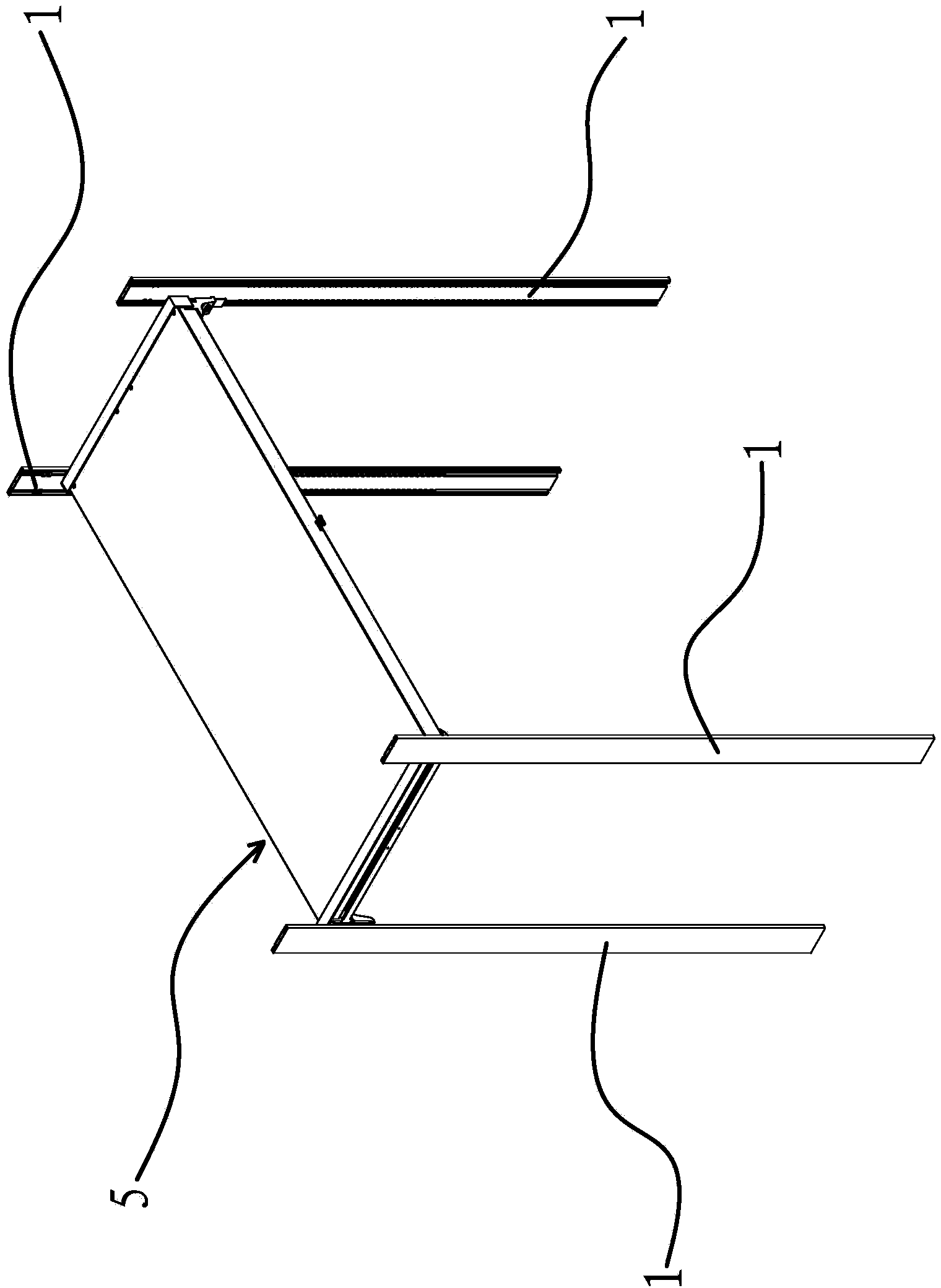
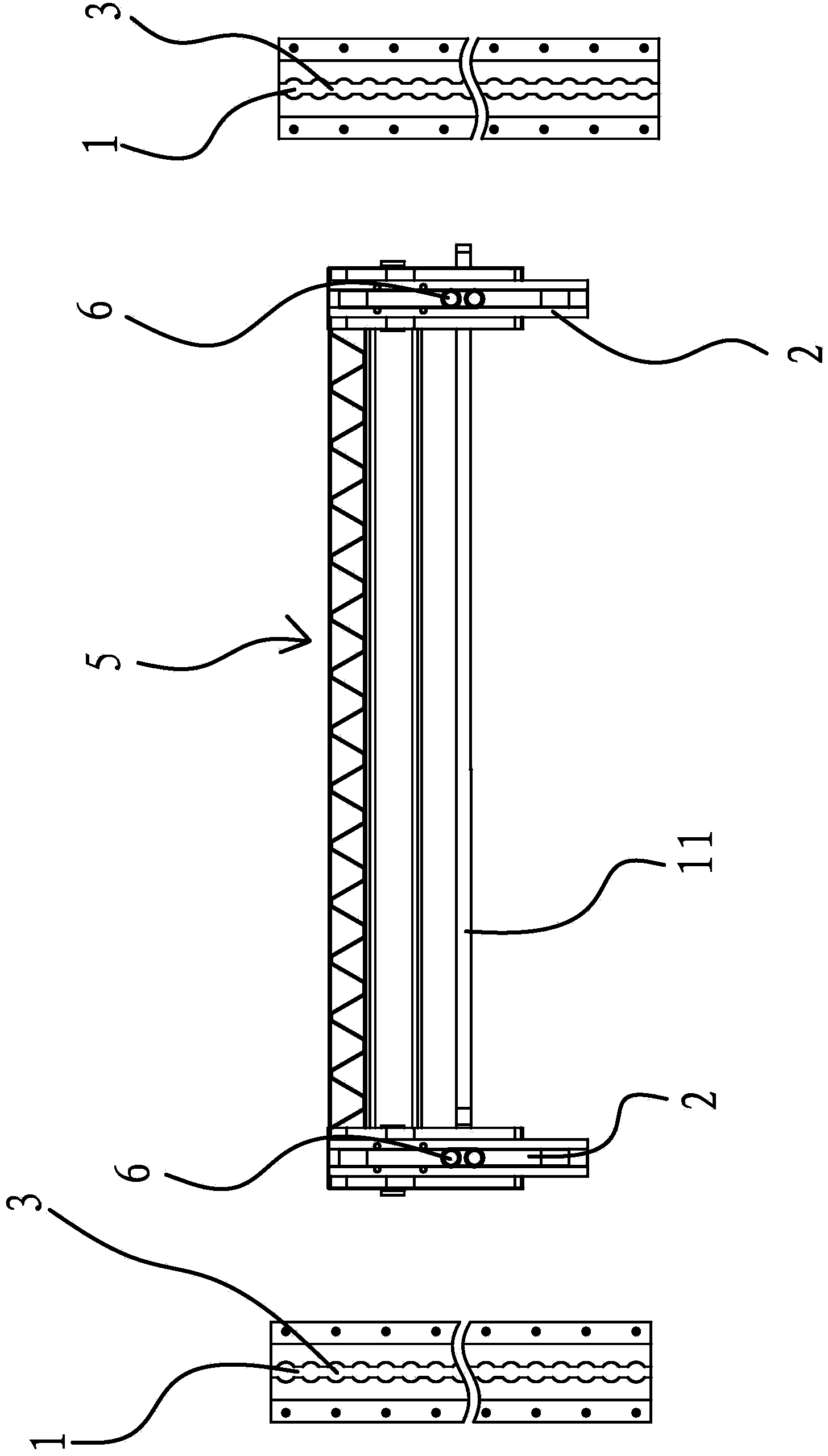
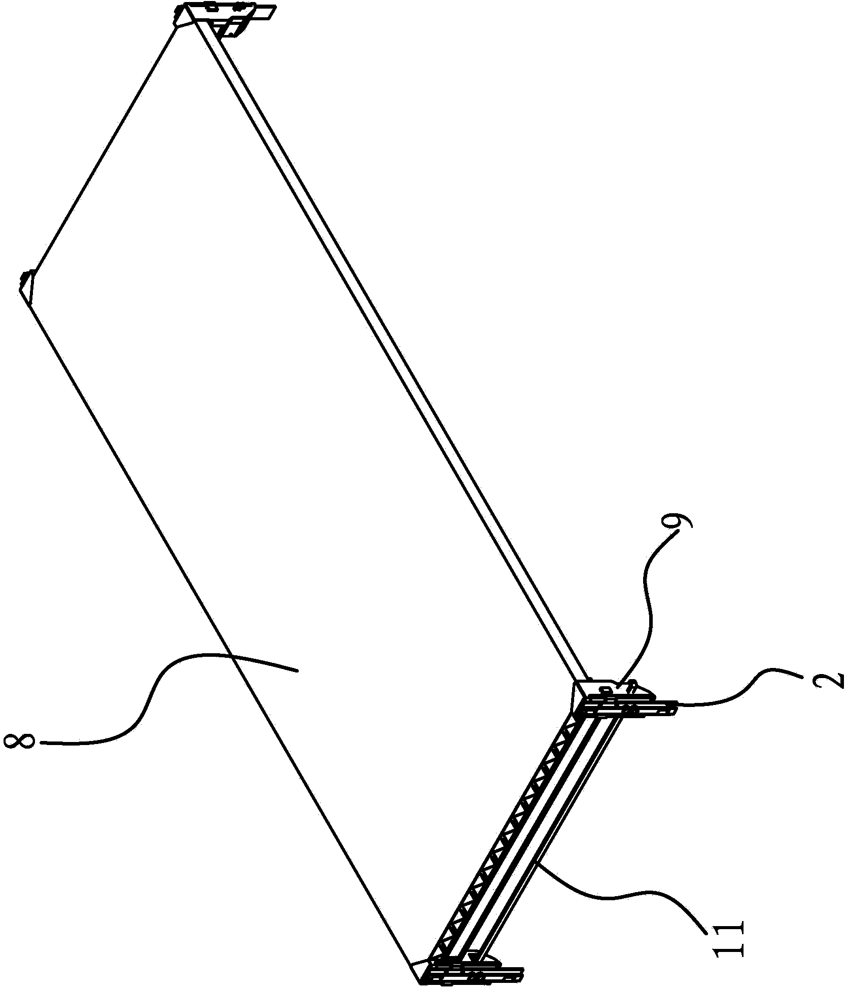
[0041] Such as figure 1 , figure 2 , image 3 , Figure 5 and Figure 9 As shown, a layering device for a carriage includes four layered guide rails 1 that are grouped in pairs and are respectively facing each other, and a connecting body 2 that is connected to each layered guide rail 1 and can slide up and down along it. 1 is provided with a number of positioning holes 3 distributed along its axial direction. Such as Figure 7 As shown, there is a protruding sliding bar 2b on the inner side of the connecting body 2, and the sliding bar 2b is located in the layered guide rail 1. The upper and lower ends of the sliding bar 2b have notches 2b1, and the notch 2b1 is connected with a plastic block that matches the shape of the notch 2b1 2b2. The connecting body 2 and the layered guide rail 1 are both made of aluminum profiles. When the sliding bar 2b of the connecting body 2 slides on the layered guide rail 1, the friction force is relatively large and it is easy to get stu...
Embodiment 2
[0051] The structure and principle of this embodiment are basically the same as that of Embodiment 1, the difference is that in this embodiment, the outside of the seat frame 4 has a positioning step 4b, and the separation layer 5 includes a positioning step connected to each adjacent two seat frames 4 The beam 7 between 4b and several supporting beams arranged in parallel, the two ends of the supporting beam are respectively lapped on the hands of the beam 7 between the two adjacent frames 4, and the two adjacent frames 4 are close to the beam 7 One side of the end is respectively connected with a sealing plate 9 . The use of multiple supporting beams can also achieve the effect of increasing the layered area. At the same time, compared with the supporting plate 8, a certain gap can be set between each supporting beam, which saves material costs while achieving layering.
Embodiment 3
[0053] The structure and principle of this embodiment are basically the same as that of Embodiment 1. The difference is that in this embodiment, a connecting plate is arranged between the mounting cavities 4a of two adjacent mounts 4, and the stop pin 6 is fixed on the connecting plate. At the end, a limit spring is arranged between the connecting plate and the mounting cavity 4a. The clutch includes a connecting rod arranged at the bottom of the support plate 8 and a wire rope connected between the connecting rod and the connecting plate. The two ends of the limiting spring respectively lean against On the connection plate and the installation cavity 4a, the wire rope passes through the rotating rod and the two ends of the wire rope are respectively connected to the connection plate between two adjacent mounts 4 . The two ends of the limiting spring respectively lean against the connecting plate and the positioning seat. Under normal conditions, the stop pin 6 is stretched out...
PUM
 Abstract
Description
Claims
Application Information
 - Generate Ideas
- Intellectual Property
- Life Sciences
- Materials
- Tech Scout
- Unparalleled Data Quality
- Higher Quality Content
- 60% Fewer Hallucinations
Browse by: Latest US Patents, China's latest patents, Technical Efficacy Thesaurus, Application Domain, Technology Topic, Popular Technical Reports.
© 2025 PatSnap. All rights reserved.Legal|Privacy policy|Modern Slavery Act Transparency Statement|Sitemap|About US| Contact US: help@patsnap.com


