Low power consumption constant current and backlight control circuit and TV

A technology of backlight control and linear constant current circuit, which is applied in the field of televisions and can solve problems such as high power consumption, increased cost, and reduced circuit efficiency

Active Publication Date: 2018-04-24
GUANGZHOU SHIKUN ELECTRONICS TECH CO LTD
View PDF4 Cites 0 Cited by
  • Summary
  • Abstract
  • Description
  • Claims
  • Application Information

AI Technical Summary

Problems solved by technology

When the linear constant current circuit works, the voltage at both ends of the switching tube will be due to the voltage error of the LED light string (generally, the range of a single LED is 2.8 to 3.4, due to the series connection of multiple LED lights, the difference between the upper limit and the lower limit of the voltage range of the LED light string will be relatively large), due to the influence of the intermodulation of the transformer (the general range is 7%), the higher the voltage, the greater the power consumption, which will cause the cost of the device to increase and the circuit efficiency to decrease
In addition, in order to reduce the temperature of the switching tube, the general switching tube will be used in parallel with multiple mos tubes or triodes, which leads to an increase in cost
[0006] In addition, when the existing technology improves the linear constant current circuit, when the power of the backlight LED is turned off, one end of the backlight LED is still connected to a useful electrical device and there is a weak current, so that the weak current is reversely connected to the backlight LED to make the backlight The LED turns on and emits a weak light, which is not allowed in the technical field of TV manufacturing

Method used


Image

  • Low power consumption constant current and backlight control circuit and TV
  • Low power consumption constant current and backlight control circuit and TV
  • Low power consumption constant current and backlight control circuit and TV

Examples


Embodiment 1

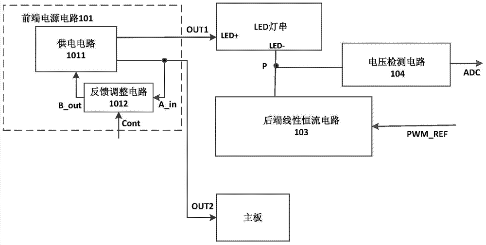
[0082] see figure 2, is a structural schematic diagram of an embodiment of the low power consumption constant current and backlight control circuit provided by the present invention.

[0083] In this embodiment, the low power consumption constant current and backlight control circuit includes a front-end power supply circuit 101 , a back-end linear constant current circuit 103 and a voltage detection circuit 104 .

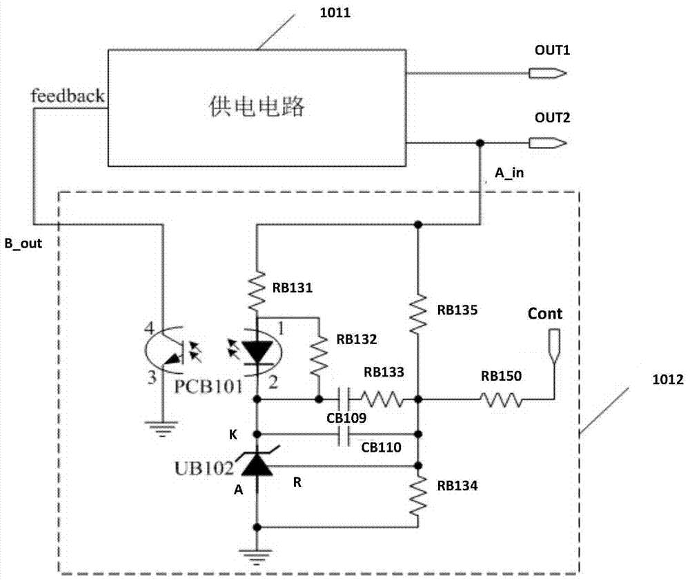
[0084] The front-end power supply circuit 101 includes a power supply circuit 1011, a first power supply output terminal OUT1, a second power supply output terminal OUT2 and a feedback adjustment circuit 1012;

[0085] Wherein, the feedback adjustment circuit 1012 includes a feedback input terminal A_in, a control signal input terminal Cont and a feedback signal output terminal B_out; the feedback input terminal A_in is connected to the second power supply output terminal OUT2, and the feedback signal output terminal B_out Connected to the power supply circuit 10...

Embodiment 2

[0129] refer to Figure 7 , is a schematic structural diagram of the second embodiment of the low power consumption constant current and backlight control circuit provided by the present invention.

[0130] In this embodiment, on the basis of Embodiment 1, further, the low power consumption constant current and backlight control circuit provided in this embodiment further includes a control main chip 105 . Among them, the basic structure and working principle of the front-end power supply circuit 101 , the back-end linear constant current circuit 103 and the voltage detection circuit 104 are the same as those of the above-mentioned embodiments, and will not be repeated here.

[0131] The control main chip 105 is respectively connected to the control signal input terminal Cont, the reference signal input terminal PWM_REF and the voltage acquisition output terminal ADC;

[0132] The control main chip 105 adjusts the magnitude of the signal output to the control signal input ter...

Embodiment 3

[0136] refer to Figure 8 , is a schematic structural diagram of the third embodiment of the low power consumption constant current and backlight control circuit provided by the present invention.

[0137] Like Embodiment 1, the low power consumption constant current and backlight control circuit of this embodiment includes a front-end power supply circuit 101 , a rear-end linear constant current circuit 103 and a voltage detection circuit 104 . Wherein, the shown front-end power supply circuit 101 and back-end linear constant current circuit 103 are consistent with the structure and working principle of Embodiment 1, and the description is omitted here. Different from Embodiment 1, the voltage detection circuit 104 of this embodiment includes a diode DB2 and a pull-up resistor RB18, the cathode of the diode DB2 is connected to the cathode LED- of the LED light string, and the anode of the diode DB2 is connected to the upper One end of the pull-up resistor RB18 is connected t...


PUM


Abstract

The invention discloses a low-power-consumption constant current and backlight control circuit. The low-power-consumption constant current and backlight control circuit comprises a front-end power source circuit and a rear-end linear constant current circuit, wherein the front-end power source circuit comprises a power supply circuit and a feedback adjustment circuit, the rear-end linear constant current circuit is provided with a connection reference signal input end to be connected with constant current reference voltage, and the rear-end linear constant current circuit and an LED light string are connected / disconnected according to the magnitude of the constant reference voltage. A voltage collecting output end is led out of the connecting position of the rear-end linear constant current circuit and the LED light string through a voltage detection circuit to collect the voltage of the connecting position, and the voltage value of a control signal input end is adjusted according to the collecting result. The voltage detection circuit is used for connecting the voltage collecting output end and the connecting position when detecting that the rear-end linear constant current circuit is connected with the LED light string and disconnecting the voltage collecting output end and the connecting position when detecting that the rear-end linear constant current output end and the LED light string are disconnected.

Description

technical field [0001] The invention relates to the technical field of power supply control, in particular to a low power consumption constant current and backlight control circuit and a television set with the low power consumption constant current and backlight control circuit. Background technique [0002] The linear constant current modulation circuit is a unit circuit widely used in analog integrated circuits, and has a wide range of applications in practice. Among them, in the field of power control technology of LED TVs, the front-end circuit is often used to output a constant voltage, and the back-end circuit is used to realize step-up or step-down constant current to realize power supply to the main board of the TV set and the LED backlight. [0003] In the process of integrating TV components, TV motherboards and backlight strips usually need to be produced together, and different numbers of backlight LED strips will require linear constant current modulation circu...

Claims


Application Information

Patent Timeline
Patent Type & Authority Patents(China)
IPC IPC(8): H04N5/44H04N5/63
Inventor 吴永芳刘威河廖武杨达富
Owner GUANGZHOU SHIKUN ELECTRONICS TECH CO LTD
Why Eureka
Try Eureka