
Method for realizing rotary floating type colorful light ball system

A realization method and technology of colored light, applied in the direction of light source, electric light source, electric light source, etc., can solve problems such as performance improvement that is not revolutionary, and achieve the effect of full fun, novel operation process and strong controllability

Active Publication Date: 2014-12-24
CHANGSHA UNIVERSITY
View PDF6 Cites 4 Cited by
  • Summary
  • Abstract
  • Description
  • Claims
  • Application Information

AI Technical Summary

Problems solved by technology

[0002] Existing LED lamps are generally used in static lamps, such as wall-mounted lamps, spotlights, table lamps, etc. Although some unique visual effects can be formed through the combination of various lamps, they are at best some application extensions to ordinary lamps. , not to mention revolutionary performance improvements, in order to pursue more brilliant and dynamic visual performance, it is necessary to design a new lighting system

Method used


Image

  • Method for realizing rotary floating type colorful light ball system
  • Method for realizing rotary floating type colorful light ball system
  • Method for realizing rotary floating type colorful light ball system

Examples


Embodiment 1

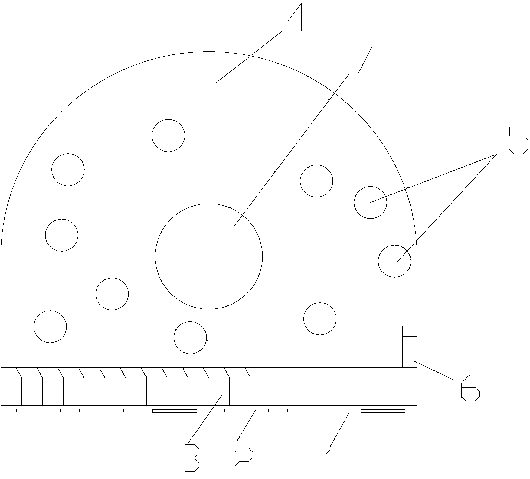
[0048] Example 1: as Figure 1-5 , an implementation method of a rotating floating color light ball system, which controls the color light ball in the box through a remote control;

[0049] The box body includes a base 1 and a transparent cover 4 buckled on the base; the top of the transparent cover is arched and the middle of the transparent cover is provided with a middle hole 7, thereby forming an annular channel between the transparent cover and the base. ; A plurality of colored light balls 5 are arranged in this channel;

[0050] A plurality of charging coils 2 are arranged inside the base; the charging coils are parallel to the bottom surface of the base;

[0051] One side of the base is provided with multiple rows of oblique jet pipes 3, and the air outlet direction of the oblique jet pipes is inclined outwards corresponding to the vertical direction; the nozzles of the adjacent oblique jet pipes are tangent; the other side of the base is provided with There are a pl...


PUM


Abstract

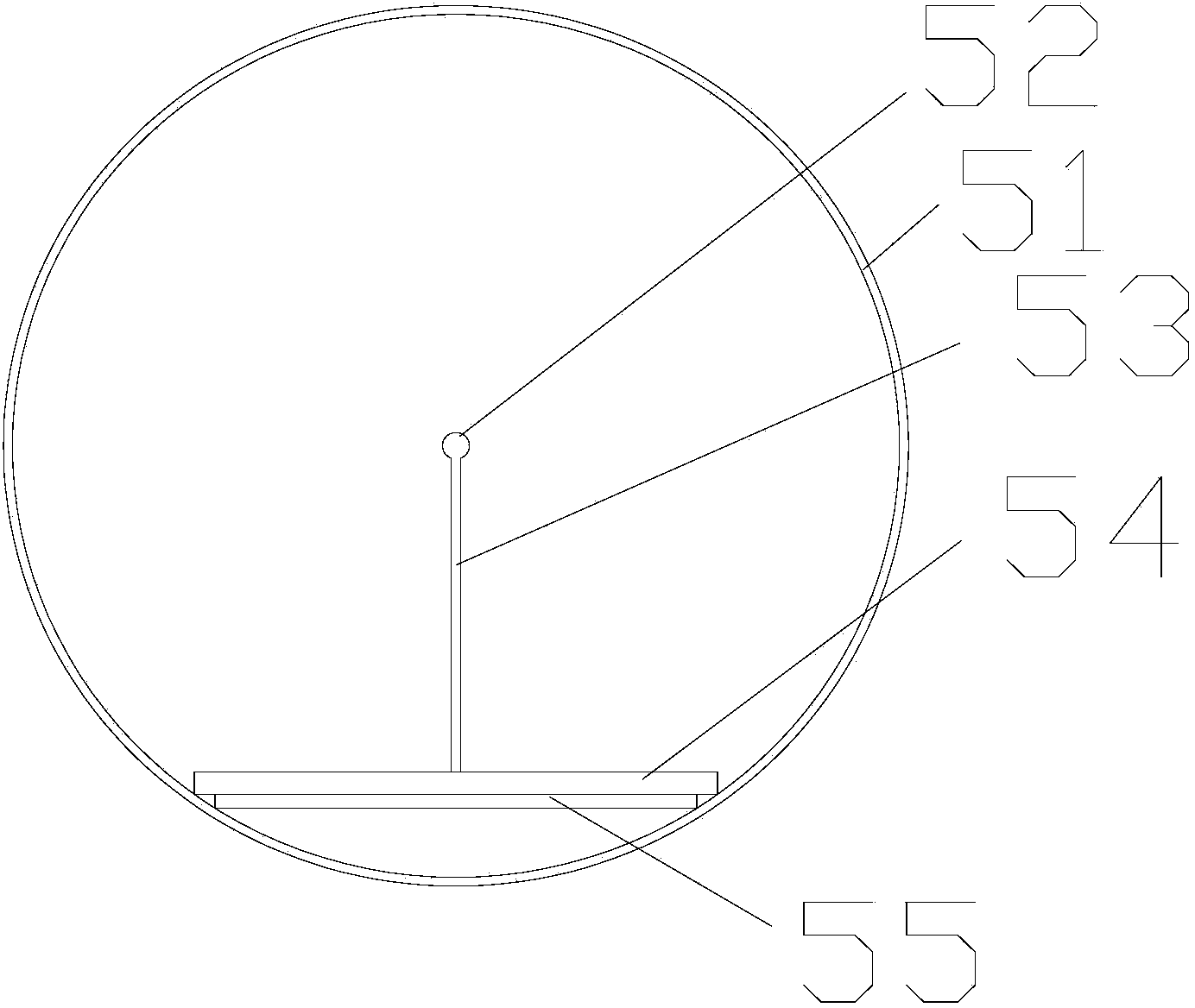
The invention discloses a method for realizing a rotary floating type colorful light ball system. The rotary floating type colorful light ball system comprises a box body and a remote controller, wherein the box body comprises a base (1) and a transparent outer cover (4) which is arranged on the base in a buckling way; an annular passage is formed between the transparent outer cover and the base; multiple colorful light balls (5) are arranged in the passage; the inner part of the base is provided with multiple charging coils (2); the base is provided with multiple rows of oblique gas ejector pipes (3) and multiple rows of transverse gas ejector pipes (6); circulating gas flow is formed in the annular passage by gas which is ejected by the oblique gas ejector pipes and the transverse gas ejector pipes and is used for driving the colorful light balls to move; each colorful light ball comprises a transparent spherical shell (51), a circuit board (54), an induction coil (55), a supporting rod (53) and a tri-color lamp (52), and the circuit board (54), the induction coil (53), the supporting rod (53) and the tri-color lamp (52) are arranged at the inner part of the transparent spherical shell. According to the method for realizing the rotary floating type colorful light ball system, disclosed by the invention, the design is clever, the implementation is easy, a dynamic and colorful visual effect can be generated by the rotary floating type colorful light ball system based on the method.

Description

technical field [0001] The invention relates to a realization method of a rotating floating color light ball system. Background technique [0002] Existing LED lamps are generally used in static lamps, such as wall-mounted lamps, spot lamps, table lamps, etc. Although some unique visual effects can be formed through the combination of various lamps, at best, they are only some application extensions of ordinary lamps and lanterns. , not to mention revolutionary performance improvements, in order to pursue a more splendid and dynamic visual performance, it is necessary to design a new lighting system. SUMMARY OF THE INVENTION [0003] The technical problem to be solved by the present invention is to provide a realization method of a rotating floating color photosphere system. The realization method of the rotating floating color photosphere system is ingenious in conception and easy to implement. The system obtained based on the method can produce dynamic and colorful Visu...

Claims


Application Information

Patent Timeline
IPC IPC(8): F21S9/02F21S10/02F21V23/00F21V33/00H05B37/02F21Y101/02
Inventor 刘亮邓名高
Owner CHANGSHA UNIVERSITY
Learn More