piercing device
A puncture needle and puncture component technology, which is applied in the fields of incontinence prevention devices, medical science, surgery, etc., can solve the problems of large trauma, damage to the urethra, infection, etc., and achieve the effect of high safety and reliable embedding
- Summary
- Abstract
- Description
- Claims
- Application Information
AI Technical Summary
Problems solved by technology
Method used
Image
Examples
no. 1 approach >
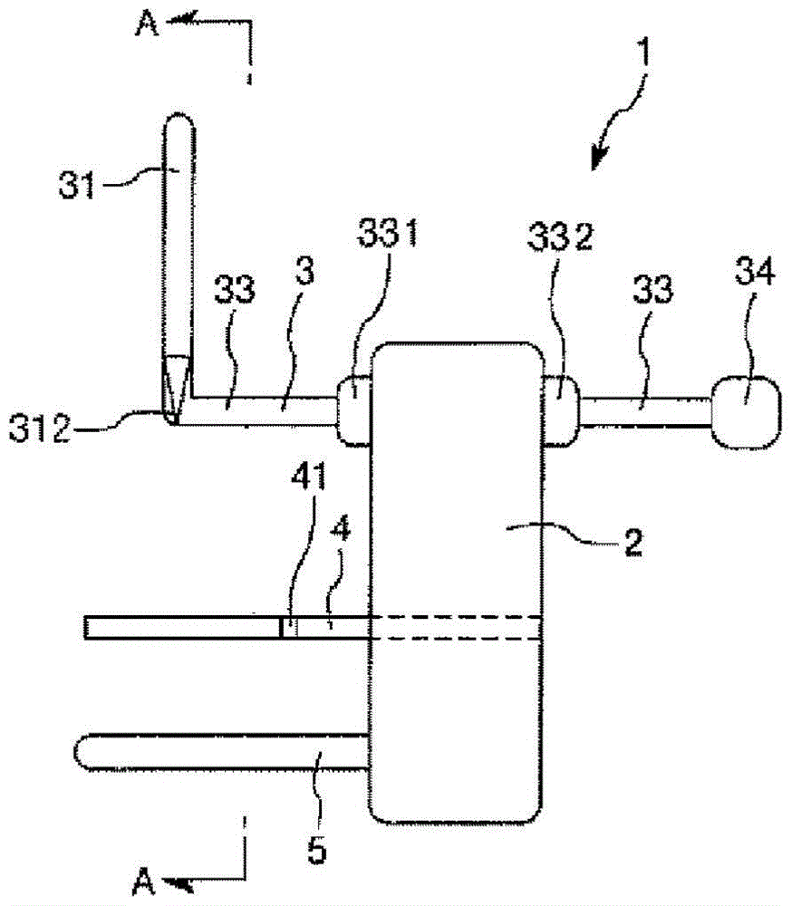
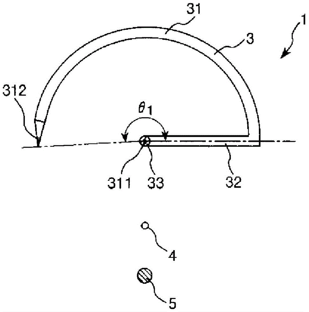
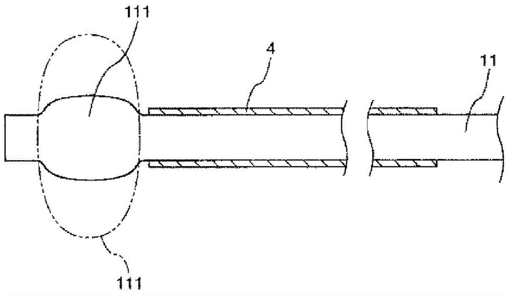
[0090] figure 1 It is a side view showing the first embodiment of the puncturing device of the present invention, figure 2 is along figure 1 The cross-sectional view of the line A-A in image 3 is expressed in figure 1 The urethral insertion part of the puncture device shown is a cross-sectional view of the state after the balloon catheter is inserted, and Fig. 4 to Fig. 7 are for illustration figure 1 A diagram of the operation steps of the piercing device shown, Figure 8 ~ Figure 11 is for illustration figure 1 Cross-sectional views of the operating steps of the piercing device shown.
[0091] also, Figure 4A , Figure 5A , Figure 6A , Figure 7A is the side view, Figure 4B is along Figure 4A The sectional view of the BB line in Figure 5B is along Figure 5A The cross-sectional view of line C-C in Figure 6B is along Figure 6A The cross-sectional view of the D-D line in Figure 7B is along Figure 7A A cross-sectional view of line E-E in . in additi...
no. 2 approach >
[0163] Figure 12 It is a side view showing the second embodiment of the puncturing device of the present invention.
[0164] In addition, the following, with Figure 12 In the illustration, the left side is "front end" and the right side is "base end".
[0165] Hereinafter, regarding the second embodiment, the description will be mainly focused on the differences from the above-mentioned first embodiment, and the description of the same items will be omitted.
[0166] like Figure 12 As shown, in the puncturing device 1 of the second embodiment, the shaft portion 33 of the puncturing member 3 is movably supported by the supporting member 2 in the axial direction of the shaft portion 33 , that is, the axial direction of the urethral insertion member 4 .
[0167] Specifically, the pricking member 3 has a tubular body 35 through which the shaft portion 33 is inserted and which supports the shaft portion 33 so as to be rotatable. In addition, flanges 331 and 332 are respectiv...
no. 3 approach >
[0176] Figure 13 It is a side view showing a third embodiment of the puncturing device of the present invention.
[0177] In addition, the following, with Figure 13 In the illustration, the left side is "front end" and the right side is "base end".
[0178] Hereinafter, the third embodiment will be described mainly focusing on the points of difference from the above-mentioned first embodiment, and the description of the same matters will be omitted.
[0179] like Figure 13 As shown, in the puncturing device 1 of the third embodiment, the axis 333 of the shaft portion 33 of the puncturing member 3 is inclined relative to the axis 42 of the urethral insertion member 4, so that the distance between the axis 333 and the axis 42 increases toward the front end. increase sideways. Thus, the implant 8 can be buried obliquely.
[0180] In addition, the axis 42 of the urethral insertion part 4 is parallel to the axis of the vaginal insertion part 5, and the axis 333 of the shaft...
PUM
 Abstract
Description
Claims
Application Information
 - R&D Engineer
- R&D Manager
- IP Professional
- Industry Leading Data Capabilities
- Powerful AI technology
- Patent DNA Extraction
Browse by: Latest US Patents, China's latest patents, Technical Efficacy Thesaurus, Application Domain, Technology Topic, Popular Technical Reports.
© 2024 PatSnap. All rights reserved.Legal|Privacy policy|Modern Slavery Act Transparency Statement|Sitemap|About US| Contact US: help@patsnap.com


