Engine

A technology of engine and turbine sensors, which is applied in the direction of combustion engine, engine control, engine components, etc., to achieve the effect of effective malfunction and reduction of computing load

Inactive Publication Date: 2014-11-05
YANMAR POWER TECHNOLOGY CO LTD +1
View PDF4 Cites 2 Cited by
  • Summary
  • Abstract
  • Description
  • Claims
  • Application Information

AI Technical Summary

Problems solved by technology

[0003] However, the previous proposals presupposed the normal operation of the aforementioned turbo sensor,

Method used


Image

  • Engine
  • Engine
  • Engine

Examples


Embodiment Construction

[0029] Next, preferred embodiments of the engine according to the present invention will be described with reference to the drawings.

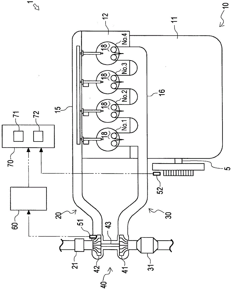
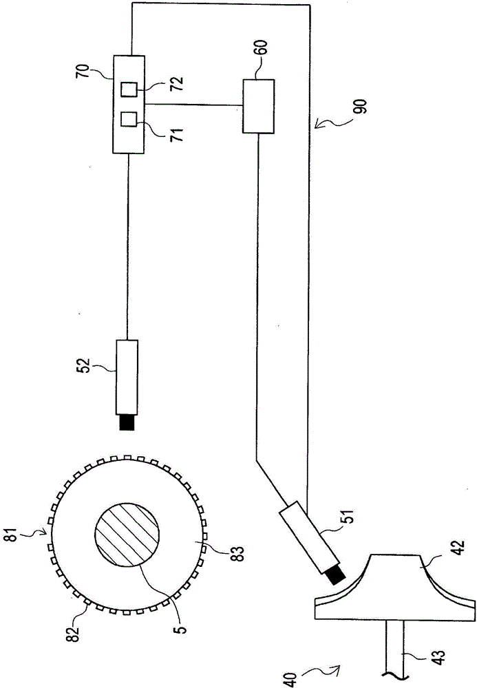
[0030] exist figure 1 In , the schematic structure of the engine 1 according to this embodiment is shown. exist figure 2 In FIG. 2 , schematic configurations of the turbine sensor 51 and the crank angle sensor 52 in the aforementioned engine 1 are shown.

[0031] Such as figure 1 and figure 2 As shown, the aforementioned engine 1 is equipped with: an engine body 10, the engine body 10 has a plurality of cylinders No.1, No.2, No.3, No.4; an intake pipeline 20, the intake pipeline 20 will Intake air is guided into the combustion chamber 18 of the aforementioned engine body 10; an exhaust line 30, which becomes a passage of exhaust gas discharged from the aforementioned combustion chamber 18; a supercharger 40, the supercharger 40 There is a turbine 41 inserted into the aforementioned exhaust pipeline 30 and a compressor 42 inserted into t...


PUM


Abstract

This engine comprises an engine main body (10) having a plurality of cylinders, an intake line (20), an exhaust line (30), a supercharger (40), a turbo sensor (51) for detecting the rotational speed of the supercharger (40), a control device (70) for controlling the operating state of the engine main body (10) which is correlated with the rotational speed of the supercharger (40) on the basis of a signal from the turbo sensor (51), and a crank angle sensor (52) for detecting the rotational angle of the crank shaft (5). The control device (70) recognizes when the plurality of cylinders are at top dead center on the basis of the detection signal of the crank angle sensor (52), and makes a determination of disconnection in the turbo sensor (51) at a non-top dead center timing during one combustion cycle of the engine main body (10), when any of the plurality of cylinders is not at top dead center.

Description

technical field [0001] The invention relates to an engine with a supercharger. Background technique [0002] In an engine having a supercharger, a turbo sensor that detects the rotational speed of the supercharger is equipped, and the operating state of the engine body having a correlation with the rotational speed of the supercharger is controlled based on a detection signal from the turbo sensor. , various proposals have been made in the past (for example, refer to Patent Documents 1 to 3). [0003] However, conventional proposals presuppose the normal operation of the turbo sensor, and there is no proposal that takes into account abnormal operation of the turbo sensor. [0004] patent documents [0005] Patent Document 1: Japanese Patent No. 4478931 [0006] Patent Document 2: Japanese Patent No. 4375369 [0007] Patent Document 3: Japanese Patent No. 4306703 Contents of the invention [0008] The present invention has been made in view of this prior art, and its o...

Claims


Application Information

Patent Timeline
IPC IPC(8): F02B39/16F02D45/00
CPCY02T10/40F02D41/222Y02T10/144F02D23/02F02D41/009F02B39/16F02D41/0007F02B37/00Y02T10/12F02D41/34
Inventor 高桥岳志板津俊郎
Owner YANMAR POWER TECHNOLOGY CO LTD
Why Eureka
Try Eureka