
Lathe bed and disc chuck temporary heating control device for warp knitting machine

A technology of heating device and machine body, which is applied in the direction of auxiliary controller with auxiliary heating device and electric temperature control, etc., which can solve the problems of cumbersome wiring, heavy workload, and bulky main electrical cabinet, etc., and achieve small size , easy to move, high application flexibility

Inactive Publication Date: 2014-11-05
KARL MAYER CHINA
View PDF6 Cites 4 Cited by
  • Summary
  • Abstract
  • Description
  • Claims
  • Application Information

AI Technical Summary

Problems solved by technology

[0002] At present, the installation accuracy requirements of warp knitting machines are very high. At the beginning of assembly, the bed and faceplate need to be heated, and the temperature can be controlled within a certain range to meet the installation accuracy requirements. It is necessary to connect the finished main electrical cabinet and supporting cables. , the wiring is cumbersome, the workload is heavy, and the working hours are long; because the machine assembly needs to be pushed forward one by one, but the main electrical cabinet is relatively heavy, and there is a cable connection between the machine and the electrical cabinet, it is inconvenient to move and not flexible enough

Method used


Image

  • Lathe bed and disc chuck temporary heating control device for warp knitting machine

Examples


Embodiment Construction

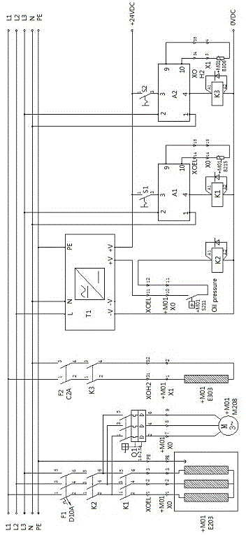
[0014] Such as figure 1 It is a structural schematic diagram of the present invention, a temporary heating control device for warp knitting machine body and faceplate, including three-phase power supply, bed heating device E203, faceplate heating device E303 and circuit control device. The circuit control device includes DC 24V power supply T1, bed Body temperature controller A1 and faceplate temperature controller A2, DC 24V power supply T1 is provided with power interface and output terminal, bed temperature controller A1 is provided with port 1, port 2, port 3, port 4, port 9 and port 10, The flower plate temperature controller A2 is provided with port 1', port 2', port 3', port 4', port 9' and port 10', the bed heating device is connected to the 380V voltage of the three-phase power supply, the bed heating device E203 is connected to all Connect the contactor K1, contactor K2 and 3P miniature circuit breaker in series between the 380V voltage of the three-phase power suppl...


PUM


Abstract

The invention relates to the technical field of heating devices, in particular to a lathe bed and disc chuck temporary heating control device for a warp knitting machine. The lathe bed and disc chuck temporary heating control device comprises a three-phase power supply, a lathe bed heating device, a disc chuck heating device and a circuit control device. The circuit control device comprises a direct current 24V power supply, a lathe bed temperature controller and a disc chuck temperature controller. The lathe bed temperature controller controls the lathe bed heating device, the disc chuck temperature controller controls the disc chuck heating device, the lathe bed and disc chuck temporary heating control device does not need to be connected with a finished main electric cabinet or a matched cable, a lathe bed and a disc chuck can be heated, and application flexibility is high; the lathe bed and the disc chuck of the machine are independently heated and can be independently controlled to be heated; the lathe bed and disc chuck temporary heating control device can be hung on an external oil circulation heating device, and is small in size and convenient to move.

Description

technical field [0001] The invention relates to the technical field of heating devices, in particular to a temporary heating control device for a warp knitting machine body and a faceplate. Background technique [0002] At present, the installation accuracy requirements of warp knitting machines are very high. At the beginning of assembly, the bed and faceplate need to be heated, and the temperature must be controlled within a certain range to meet the installation accuracy requirements. It is necessary to connect the finished main electrical cabinet and supporting cables. , the wiring is cumbersome, the workload is heavy, and the working hours are long; because the machine assembly needs to be pushed forward one by one, but the main electrical cabinet is relatively heavy, and there is a cable connection between the machine and the electrical cabinet, it is inconvenient to move and not flexible enough. Contents of the invention [0003] In order to overcome the existing ab...

Claims


Application Information

Patent Timeline
Patent Type & Authority Applications(China)
IPC IPC(8): G05D23/30
Inventor 薛枫
Owner KARL MAYER CHINA
Learn More