
A multi-working condition bridge inspection vehicle

A bridge inspection vehicle, multi-working condition technology, applied in bridges, bridge parts, bridge construction and other directions, can solve the problems of delay in construction period, loss of manpower for dismantling and assembling sound insulation walls, affecting the efficiency of bridge inspection vehicles, etc., to achieve the ability to achieve width , the effect of high ability improvement

Active Publication Date: 2016-02-17
XCMG XUZHOU TRUCK MOUNTED CRANE
View PDF5 Cites 2 Cited by
  • Summary
  • Abstract
  • Description
  • Claims
  • Application Information

AI Technical Summary

Problems solved by technology

[0003] For traditional bridge inspection vehicles, the slewing mechanism is integrally fixed. This structure determines that the spanning capacity of the bridge inspection vehicle cannot be adjusted and is at a relatively low level.
Nowadays, as urban managers and residents gradually increase the noise control requirements of highway bridges, more and more bridges have begun to install sound insulation walls on the side of the bridge. The span height of the bridge inspection vehicle can only reach 2.5m~3m. If you need to inspect such bridges, you must first remove the sound insulation wall on the side of the bridge, and then restore the sound insulation wall after the inspection is completed.
In addition to the loss of human, material and financial resources, the disassembly and assembly of the sound insulation wall will also cause delays in the construction period and seriously affect the efficiency of the bridge inspection vehicle.

Method used


Image

  • A multi-working condition bridge inspection vehicle
  • A multi-working condition bridge inspection vehicle

Examples


Embodiment Construction

[0022] The present invention will be further described below in conjunction with drawings and embodiments.

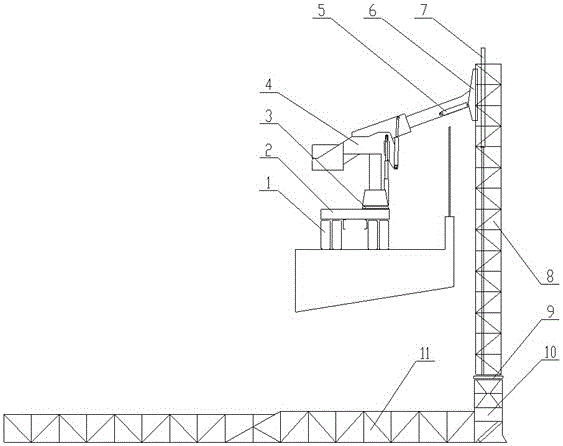
[0023] Such as figure 1 As shown, a multi-working condition bridge inspection vehicle of the present invention includes a chassis 1, a first slewing mechanism 4, an overturning mechanism 6, a lifting cylinder 7, a vertical arm 8, a second slewing support 9, a second slewing mechanism 10 and a telescopic arm 11;

[0024] The chassis 1 provides a carrier for the working device of the bridge inspection vehicle; at the same time, the power of the chassis engine can be sent to the working device as the source power through the power output of the chassis engine.

[0025] A subframe 2 is installed on the chassis 1, and a first slewing bearing 3 is installed on the subframe 2. The subframe 2 bears the part above the first slewing bearing 3, and transmits its force to the girder of the chassis 1. It also provides space for the arrangement of other accessories of the vehicle. ...


PUM


Abstract

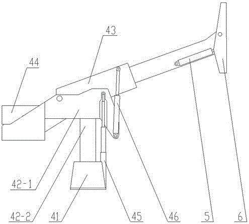
The invention discloses a multi-working-condition bridge detecting vehicle, and belongs to the technical field of bridge detecting. The multi-working-condition bridge detecting vehicle comprises a chassis (1), an auxiliary frame (2), a turnover mechanism (6), a lifting oil cylinder (7), a vertical arm (8), a second slewing bearing (9), a second slewing mechanism (10) and a telescopic arm (11). A first slewing mechanism (4) is installed on a first slewing bearing (3) and an amplitude-changing oil cylinder (5) which can adjust the turnover angle is arranged between the first slewing mechanism and the turnover mechanism (6). The first slewing mechanism is mainly composed of a base (41), a connecting body, a main arm (43), slewing lifting oil cylinders (45) and slewing amplitude-changing oil cylinders (46). According to the multi-working-condition bridge detecting vehicle, functions of the first slewing mechanism are divided, a plurality of independent units are integrated to form the first slewing mechanism, mutual motion mechanisms between the units are arranged, therefore, three freedom degrees, namely, lifting, amplitude changing and stretching and contracting, are newly added to the first slewing mechanism, the vertical striding capacity and the horizontal striding capacity of the detecting vehicle are greatly improved and the application range of the detecting vehicle is expanded.

Description

technical field [0001] The invention relates to a bridge inspection vehicle, in particular to a bridge inspection vehicle with multiple working conditions, belonging to the technical field of bridge inspection. Background technique [0002] According to the QC / T826-2010 bridge inspection vehicle industry standard, the main structural parameters to measure the working performance of the truss bridge inspection vehicle (referred to as the bridge inspection vehicle) include the maximum horizontal operating range, the maximum operating depth of the working platform, the height of the guardrail and the span sidewalk width etc. Among them, the height of crossing the guardrail and the width of crossing the sidewalk are collectively referred to as the spanning capacity of the bridge inspection vehicle, which determines the operating capacity and scope of application of the bridge inspection vehicle when operating on the bridge. [0003] In the traditional bridge inspection vehicle,...

Claims


Application Information

Patent Timeline
Patent Type & Authority Patents(China)
IPC IPC(8): E01D19/10
Inventor 程磊单龙邱剑飞陈志伟李根文张雷陈城胡志林孔令燕李波
Owner XCMG XUZHOU TRUCK MOUNTED CRANE
Learn More