A method for monitoring and adjusting the liquid level stability of etching tank

An etching tank and stability technology, applied in electrical components, circuits, semiconductor/solid-state device testing/measurement, etc., can solve problems such as liquid level gradient or poor liquid level stability, irregular etching and debugging results, etc. To achieve the effect of convenient observation and reading, speeding up the adjustment speed

Active Publication Date: 2016-08-24
泗阳腾晖光电有限公司 +1
View PDF4 Cites 0 Cited by
  • Summary
  • Abstract
  • Description
  • Claims
  • Application Information

AI Technical Summary

Problems solved by technology

Roller 5 is generally installed and debugged by professionals, and is regularly maintained. Its state is relatively stable; the mixed solution includes two aspects: concentration and liquid level, and the concentration of the mixed solution generally remains stable due to the existence of molecular diffusion in the solution, while etching The gradient or stability of the liquid level in tank 2 directly affects the etching quality. An unreasonable liquid level gradient or poor liquid level stability will directly cause the solution to erode the front surface of the silicon wafer 8, resulting in poor over-engraving or the inability of the solution to adsorb to the silicon. Insufficient etch caused by the edge of sheet 8
The current etching process lacks the measurement and monitoring of the liquid level stability or liquid level gradient of the etching tank, which often affects the liquid level of the liquid inlet pipe 6, the angle of the air outlet 7, the front baffle 3 and the rear The height of the baffle plate 4 is adjusted blindly, but it is impossible to know how much the direct result of the adjustment (liquid level height, liquid level gradient) has changed, resulting in irregular debugging results and increased difficulty and time to solve process problems

Method used


Image

  • A method for monitoring and adjusting the liquid level stability of etching tank
  • A method for monitoring and adjusting the liquid level stability of etching tank

Examples


Embodiment 1

[0025] This embodiment provides a method for monitoring and adjusting the liquid level stability of the etching tank, which includes the following steps in sequence:

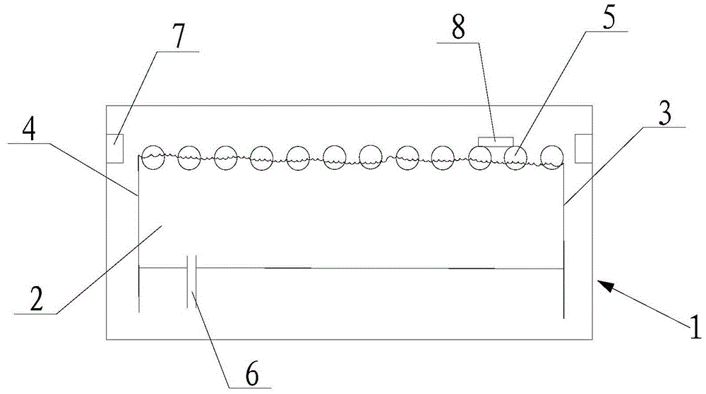
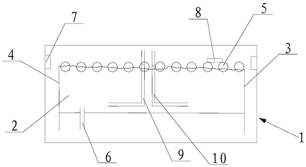
[0026] (a) Select two test points A and B at different positions of the etching tank, and respectively place the first liquid level gauge 9 and the second liquid level gauge 10 at the test points (the first liquid level gauge 9 and the second liquid level gauge The liquid level gauge 10 is made of acid and alkali-resistant Teflon transparent material, with a diameter of 5mm~20mm and a minimum scale of 0.5mm, which is conducive to prolonging the service life on the one hand and precise control on the other hand). The standard liquid level height Hs at the two test points when the state is stable A 、H sB And the standard liquid level tolerance ΔH of the test point s , the standard liquid level tolerance ΔH of the etching equipment is used in this embodiment s =2mm;

[0027] (b) Start the etching equipment so t...


PUM


Abstract

The invention relates to a method for monitoring and adjusting the stability of the liquid level of an etching trough. The method sequentially comprises the following steps that (a) a liquid level instrument is placed at each test point, and the standard liquid level height Hs and the standard liquid level tolerance delta Hs at each test point are recorded; (b) the liquid level height Hn at each test point is recorded, and when the absolute value of the difference between the liquid level height Hn at each test point and the standard liquid level height Hs of the corresponding test point exceeds the standard liquid level tolerance delta Hs, the heights of a front baffle and a rear baffle, the opening degree of an air outlet and the liquid inlet quantity of an agent inlet pipe of the etching trough are adjusted correspondingly; (c) when the absolute value of the difference between the liquid level height Hn at each test point and the standard liquid level height Hs of the corresponding test point exceeds the standard liquid level tolerance delta Hs, the step (b) is repeated. In this way, on one hand, the liquid level condition of the etching trough can be monitored in a quantitative mode, and a direct and effective method is provided for control over the process stability of the etching trough; on the other hand, the liquid level of the etching trough can be adjusted regularly, and the rate of adjusting the liquid level of the etching trough is increased.

Description

technical field [0001] The invention belongs to the field of wet etching technology of photovoltaic crystalline silicon solar cells, relates to a method for monitoring and adjusting the liquid level stability of a solution, in particular to a method for monitoring and adjusting the liquid level stability of an etching tank. Background technique [0002] The etching process is an indispensable and important process in the production process of crystalline silicon solar cells. During the diffusion process, even if the back-to-back single-sided diffusion method is adopted, all surfaces (including edges) of the silicon wafer will inevitably be diffused with phosphorus. . The photo-generated electrons collected on the front side of the PN junction will flow to the back side of the PN junction along the area where the phosphor is diffused along the edge, causing a short circuit. This short path is equivalent to reducing the parallel resistance. After the etching process, the pho...

Claims


Application Information

Patent Timeline
Patent Type & Authority Patents(China)
IPC IPC(8): H01L21/66
CPCH01L22/20
Inventor 任军林陆银川黄浩陈志陈浩魏青竹
Owner 泗阳腾晖光电有限公司
Why Eureka
Try Eureka