
Vehicle front structure

A front structure and vehicle technology that is applied to the upper structure, lower structure, and vehicle parts, and can solve problems such as impact load obstruction and difficulty in ensuring the movement of the power unit

Inactive Publication Date: 2014-09-10
HONDA MOTOR CO LTD
View PDF9 Cites 6 Cited by
  • Summary
  • Abstract
  • Description
  • Claims
  • Application Information

AI Technical Summary

Problems solved by technology

[0012] Therefore, it is difficult to ensure the amount of movement of the power unit to the rear of the vehicle, which hinders sufficient absorption of impact loads.

Method used


Image

  • Vehicle front structure
  • Vehicle front structure
  • Vehicle front structure

Examples


Embodiment Construction

[0051] Hereinafter, the best mode for carrying out the present invention will be described based on the drawings. In addition, "front (Fr)", "rear (Rr)", "left (L)", and "right (R)" correspond to the direction seen from a driver.

[0052] 【Example】

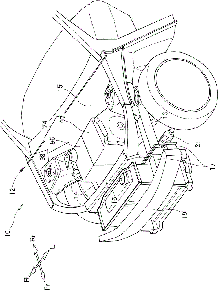
[0053] The vehicle front structure 12 of the embodiment will be described.

[0054] Such as figure 1 , figure 2 As shown, vehicle 10 is provided with a vehicle front structure 12 forming the front of vehicle 10 .

[0055]The vehicle front structure 12 includes: left and right side frames 13, 14 provided at the front of the vehicle 10; dash panels 15 provided at the rear ends 13a, 14a of the left and right side frames 13, 14; the front bulkhead 16 provided at the front end portions 13b, 14b of the side frames 13, 14; and the left and right connecting members 17 (see also image 3 ) and the front bumper 19 connected to the front end portions 13b, 14b of the left and right side frames 13, 14.

[0056] In addition, the vehicle ...


PUM


Abstract

A vehicle front structure includes left and right side frames and a sub-frame disposed below the left and right side frames. The sub-frame includes a cross member, which connects rear end portions of left and right side members, and a support unit, which supports a steering gear box at front end portions of the left and right side members. The steering gear box is supported by the support unit so as to be located in a vehicle-front-side region of the power plant. The support unit is capable of being broken by an impact load so that the steering gear box is dropped when the impact load is applied.

Description

technical field [0001] The invention relates to a front structure of a vehicle which is provided with a steering gear box on the sub-frame and a power device above the sub-frame. Background technique [0002] Among vehicle front structures, there is known a structure in which left and right front side members extend along the vehicle front-rear direction, left and right extensions extend from the middle of the left and right front side members toward the inside in the vehicle width direction, and the left and right extensions A steering gear box is mounted on the top (for example, refer to Patent Document 1). [0003] By erecting the steering gear box on the left and right extensions, the steering gear box can also be used as a beam. Thereby, the beam can be eliminated, so that the weight of the vehicle can be reduced. [0004] However, the steering gear box of Patent Document 1 extends in the vehicle width direction along the dash panel. The engine compartment is separat...

Claims


Application Information

Patent Timeline
IPC IPC(8): B62D21/09B62D21/00
CPCB62D21/155B62D25/082B62D21/11B62D3/12
Inventor 粟野克行弥武朋也
Owner HONDA MOTOR CO LTD
Learn More