Locking mechanism

A technology of locking mechanism and locking parts, applied in the direction of electrical components, base/housing, coupling device, etc., can solve the problems of customer uncertainty, lower reliability, different reliability, etc., to save maintenance labor costs and material costs, Prevent accidental unlocking and easy operation

Inactive Publication Date: 2014-07-23
TYCO ELECTRONICS (SHANGHAI) CO LTD
View PDF3 Cites 10 Cited by
  • Summary
  • Abstract
  • Description
  • Claims
  • Application Information

AI Technical Summary

Problems solved by technology

[0021] 1. A locking mechanism of the same series only connects a plug connector-socket connector assembly of the same series, and products of different series cannot be connected; therefore, there is no wide range of versatility, interchangeability, and intermatability Inconvenience, replacement and compatibility for customers, increased customer inventory and cost;
[0022] 2. The locking mechanical principles of different locking mechanisms are different, the locking force is different, and the reliability is also different. Therefore, it brings uncertainty to customers and reduces reliability;
[0023] 3. The connection force is generated by manual pulling, which increases the labor intensity of the operator and increases the risk of misoperation;
[0024] 4. All the above-mentioned locking mechanisms are pivotally connected to the plug connector or socket connector and cannot be separated independently. Therefore, for customers, maintenance is inconvenient. In some cases, the only option is to scrap the entire product. Instead of just scrapping the locking mechanism, keep the plug and socket connectors working; and
[0025] 5. In terms of the function of ensuring the IP65 waterproof level, the sealing is very simple and the reliability is poor

Method used


Image

  • Locking mechanism
  • Locking mechanism
  • Locking mechanism

Examples


Embodiment Construction

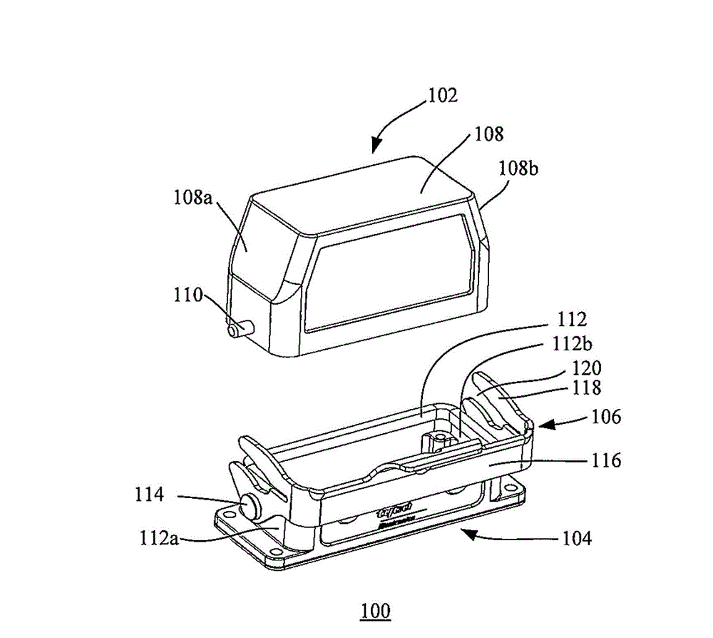
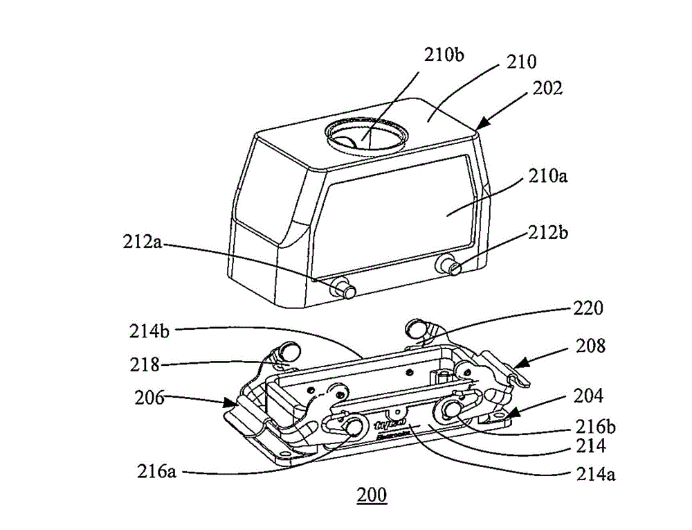
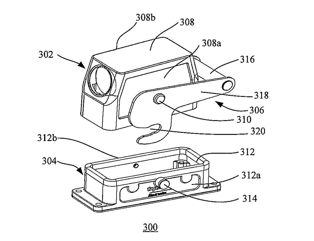
[0057] In the following detailed description of the embodiments, reference is made to the accompanying drawings that form a part hereof. The drawings show, by way of example, specific embodiments in which the invention may be practiced. The illustrated embodiments are not intended to be exhaustive of all embodiments according to the invention. It is to be understood that other embodiments may be utilized and structural or logical changes may be made without departing from the scope of the present invention. With respect to the drawings, directional terms such as "left," "right," "bottom," "front," "back," "downward," "upward," etc., are intended with reference to the orientation of the drawings being described. in use. Since components of embodiments of the present invention can be orientated in a variety of ways, these directional terms are used for purposes of description, not limitation. Accordingly, the following detailed description is not intended to be limiting, and ...


PUM


Abstract

The invention discloses a locking mechanism used for locking an upper connector and a lower connector. The outer surface of the upper connector is provided with a first rod-shaped abutting part, and the outer surface of the lower connector is provided with a second rod-shaped abutting part. The locking mechanism comprises an annular locking piece accommodating shell, an upper locking piece and a lower locking piece, wherein the annular locking piece accommodating shell is provided with a side wall sleeving the upper connector and the lower connector, the upper side of the side wall is provided with an opened upper trench and the lower side is provided with an opened lower trench; the upper locking piece is arranged inside the upper trench and used for removably locking the first rod-shaped abutting part inside the upper trench; and the lower locking piece is arranged inside the lower trench and used for removably locking the second rod-shaped abutting part inside the lower trench.

Description

technical field [0001] The invention relates to a locking mechanism, in particular to a locking mechanism applied to a heavy-duty plug connector and a heavy-duty socket connector. Background technique [0002] Such as figure 1 As shown, it shows an existing HTS heavy-duty connector 100 , the connector 100 includes a plug connector 102 , a receptacle connector 104 and a locking mechanism 106 connecting the plug connector 102 and the receptacle connector 104 . Specifically, the plug connector 102 includes a plug housing 108 and a rivet 110 protrudes from each of two side surfaces 108 a , 108 b of the plug housing 108 . The receptacle connector 104 includes a receptacle housing 112 and a rivet 114 protruding from each of two side surfaces 112 a , 112 b of the receptacle housing 112 . The locking mechanism 106 is pivotally connected to the rivet 114 of the socket connector 104 to rotate around the rivet 114 . Specifically, the locking mechanism 106 includes a handle portion 1...

Claims


Application Information

Patent Timeline
Patent Type & Authority Applications(China)
IPC IPC(8): H01R13/639H01R13/52
CPCH01R13/6275H01R13/629
Inventor 李沈平汪浩
Owner TYCO ELECTRONICS (SHANGHAI) CO LTD
Why Eureka
Try Eureka