
Let-off device of air jet loom

An air-jet loom and warp let-off technology, applied in looms, textiles, textiles and papermaking, etc., can solve the problems of reduced service life, reduced overall performance of looms, large difference in warp tension, etc., to improve overall machine performance, The effect of solving the difficulty in adjusting the amount of loose warp and the loose warp time and the reasonable structure of the loom

Active Publication Date: 2014-07-02
QINGDAO TIANYI GROUP RED FLAG TEXTILE MACHINERY
View PDF9 Cites 5 Cited by
  • Summary
  • Abstract
  • Description
  • Claims
  • Application Information

AI Technical Summary

Problems solved by technology

At present, whether it is a positive let-off device or a negative tension mechanism, in order to ensure the rigidity of the tension roller, the support points of the tension roller are all on the inner side of the roller support frame, that is, the power of the device is set on the loom wallboard. Although such a structural design ensures the rigidity of the roller, it cannot solve the problem that the loosening time of the loosening amount is difficult to adjust, and the whole machine mechanism is not reasonable, which reduces the overall performance of the loom
Some air-jet looms solve the above problems by directly lengthening the back beam to extend to the outside of the roller support. However, due to the lengthening of the roller, the weight increases and the rigidity is weakened, the deformation of the roller causes a large difference in the tension of the warp yarn, and the machine parts wear quickly. , reduced lifespan

Method used


Image

  • Let-off device of air jet loom
  • Let-off device of air jet loom
  • Let-off device of air jet loom

Examples


Embodiment Construction

[0031] The present invention will be further described in detail below in conjunction with the accompanying drawings and specific embodiments, but the present invention is not limited to these embodiments.

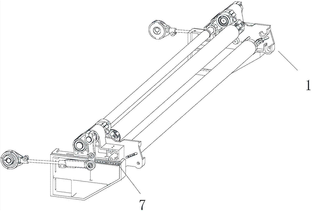
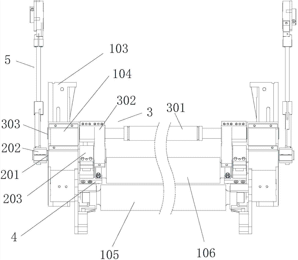
[0032] Such as Figure 1 to Figure 6 As shown, a let-off device for an air-jet loom includes a frame 1, and the frame 1 includes a left frame 101 and a right frame 102 with the same structure, and scale plates are arranged on the outside of the left and right frames 7. A tension roller 106 and a transition roller 105 are installed between the left and right frames. The left and right frames all include a lifting support 103 and a positioning seat 104 installed above the lifting support 103; the two positioning seats 104 are respectively Tension roller supporting mechanism 2 is installed, and each tension roller supporting mechanism 2 all comprises rocking shaft 201, and one end of each rocking shaft 201 is all equipped with rocking arm 202, and the other end is all equippe...


PUM


Abstract

The invention discloses a let-off device of an air jet loom. The let-off device comprises a left machine frame and a right machine frame, wherein the left machine frame and the right machine frame are the same in structure. A tension roller and a transition roller are installed between the left machine frame and the right machine frame. The left machine frame and the right machine frame respectively comprise a lifting support and a positioning base installed on the upper portion of the lifting support. The two positioning bases are respectively provided with a tension roller supporting mechanism. The tension roller supporting mechanisms respectively comprise a rocking shaft, a rocking arm is installed at one end of each rocking shaft, a movable supporting arm is installed at the other end of each rocking shaft, the rocking arms are located outside the left machine frame and the right machine frame, the movable supporting arms are located inside the left machine frame and the right machine frame, the outer sides of the rocking arms are connected with positive warp loosening mechanisms or negative tension mechanisms, and the movable supporting arms are respectively provided with a lining and a bearing for installing the tension roller. Power of the positive warp loosening mechanisms or the negative tension mechanisms is transmitted to the inner sides of the machine frames from the outer sides of the machine frames, and the complete air jet loom is reasonable in mechanism and stable and reliable in performance.

Description

technical field [0001] The invention relates to an air-jet loom, in particular to a let-off device for an air-jet loom. Background technique [0002] The function of the let-off device of the air-jet loom in the whole weaving process is to send out quantitative warp yarns with a certain tension in time during the weaving process according to the requirements of the weaving density of the fabric structure, so as to maintain the continuous production of weaving. In the weaving process, whether the warp tension is uniform when the weaving beam changes from large to small is the main standard to measure the performance of the let-off device, and the size and stability of the warp tension depend to a large extent on the let-off amount. the size of. Some weaving defects of the fabric are caused by uneven let-off. For example, cloud weaving is caused by uneven let-off of short segments, and long and short codes are caused by uneven let-off of long segments. The performance of the...

Claims


Application Information

Patent Timeline
IPC IPC(8): D03D49/06D03D49/18
Inventor 齐立民范龙霄丁尚云吴海艳霍艳慧
Owner QINGDAO TIANYI GROUP RED FLAG TEXTILE MACHINERY
Learn More