
Infrared device installation criterion validity method and installation criterion validity system

An equipment installation, infrared technology, applied in the field of testing

Active Publication Date: 2014-06-25
北京航天晨信科技有限责任公司
View PDF4 Cites 2 Cited by
  • Summary
  • Abstract
  • Description
  • Claims
  • Application Information

AI Technical Summary

Problems solved by technology

[0003] The invention provides an infrared device installation standard effect method and an installation standard effect system to solve the problem of how to ensure that the infrared device can accurately aim at the target when the installation structure of the infrared device is fixed

Method used


Image

  • Infrared device installation criterion validity method and installation criterion validity system
  • Infrared device installation criterion validity method and installation criterion validity system
  • Infrared device installation criterion validity method and installation criterion validity system

Examples


Embodiment 1

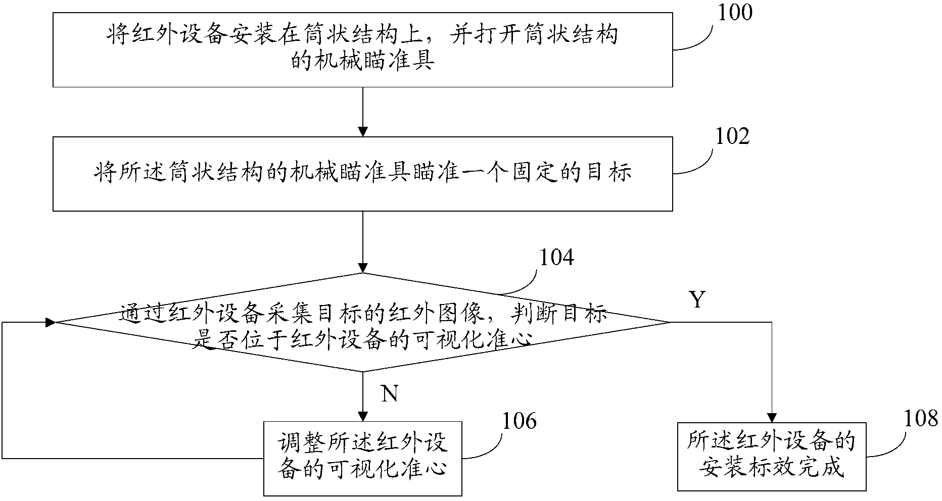
[0045] refer to figure 1 , which shows a flow chart of a method for installing an infrared device according to the present invention, and this embodiment may specifically include the following steps:

[0046] Step 100, installing the infrared device on the cylindrical part, and opening the mechanical sight of the cylindrical part;

[0047] After installing the infrared device on the cylindrical part and opening the mechanical sight of the cylindrical part, since the mechanical sight is installed on the cylindrical part itself, the shooter can use the infrared device and the mechanical sight on the cylindrical part to simultaneously Observe the target.

[0048] Step 102, aiming the mechanical sight of the cylindrical part at a fixed target;

[0049] In this embodiment, a distant fixed target can be selected, so that the cylindrical component can be stably aimed at the target through the mechanical sight. Choose a fixed target, iron sights can be easier to aim than moving tar...

Embodiment 2

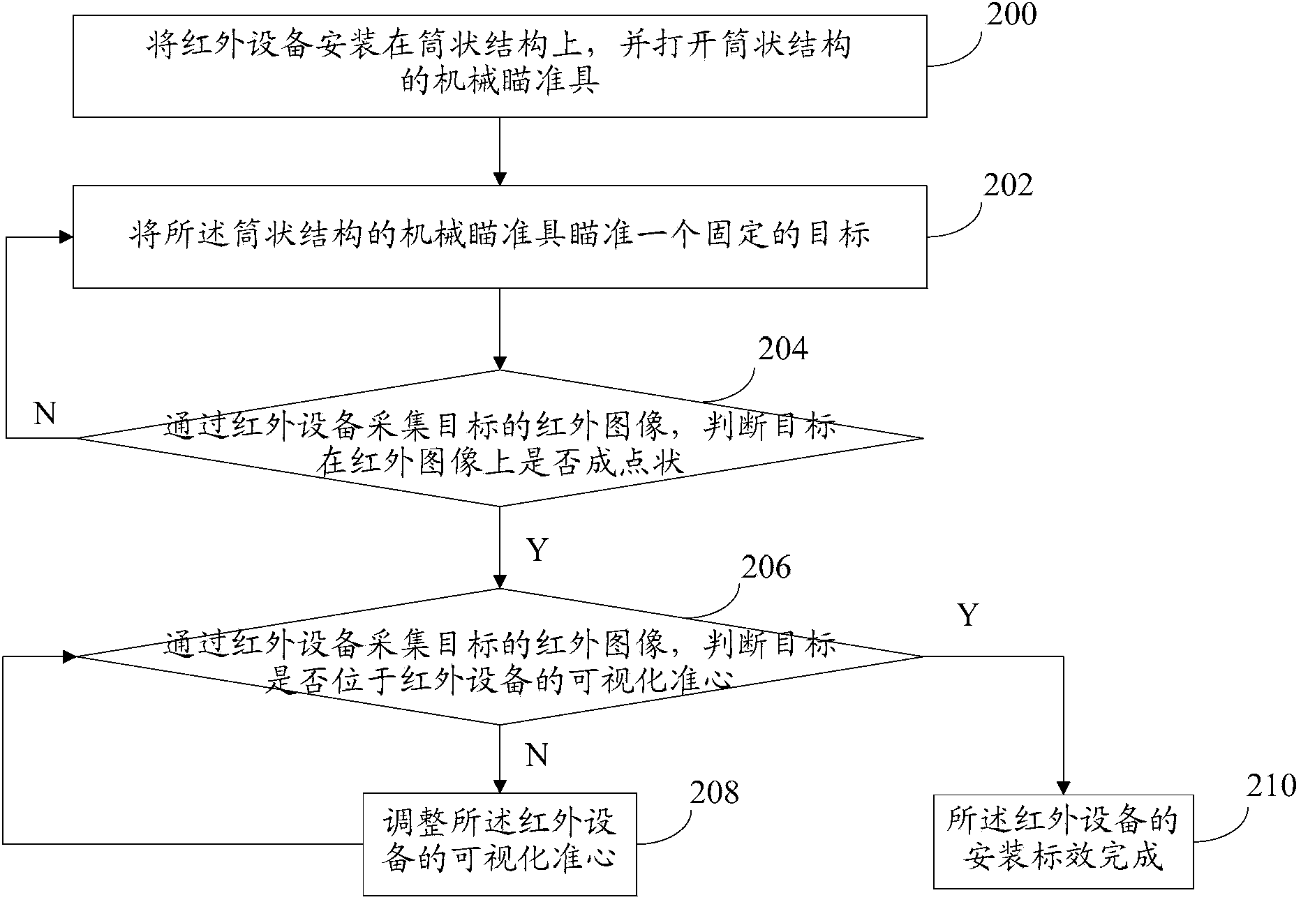
[0059] refer to figure 2 , which shows a flow chart of another method for installing an infrared device according to the present invention, and this embodiment may specifically include the following steps:

[0060] Step 200, installing the infrared device on the cylindrical part, and opening the mechanical sight of the cylindrical part;

[0061] After installing the infrared device on the cylindrical part and opening the mechanical sight of the cylindrical part, since the mechanical sight is installed on the cylindrical part itself, the shooter can use the infrared device and the mechanical sight on the cylindrical part to simultaneously Observe the target.

[0062] Step 202, aiming the mechanical sight of the cylindrical part at a fixed target;

[0063] In this embodiment, a distant fixed target can be selected, so that the cylindrical component can be stably aimed at the target through the mechanical sight. Choose a fixed target, iron sights can be easier to aim than mov...

Embodiment 3

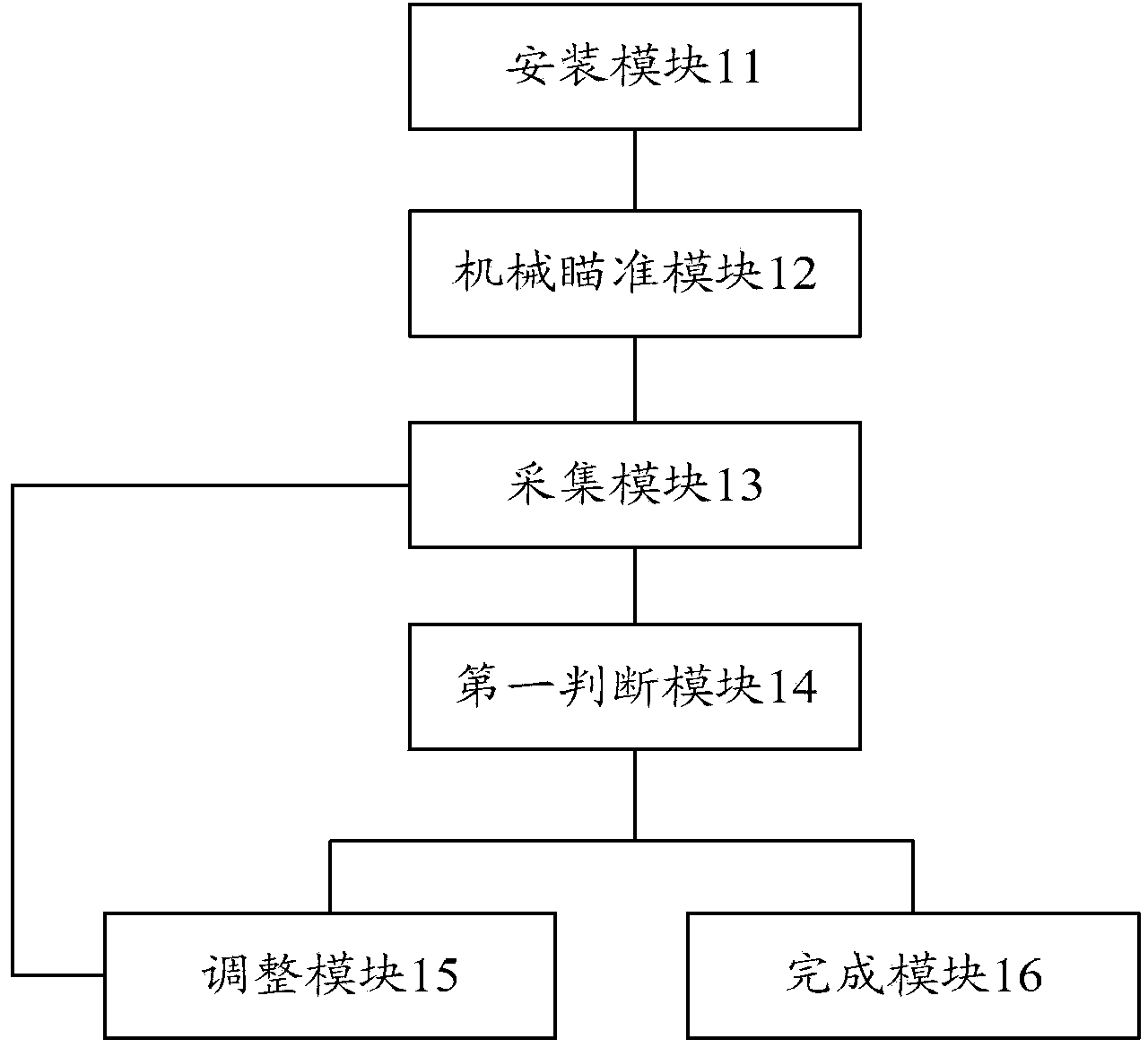
[0082] refer to image 3 , which shows a structural block diagram of an infrared device installation standard effect system according to the present invention, and this embodiment may specifically include the following modules:

[0083] The installation module 11 is used to install the infrared device on the cylindrical part and open the mechanical sight of the cylindrical part;

[0084] After the installation module 11 installs the infrared device on the cylindrical part and opens the mechanical sight of the cylindrical part, since the mechanical sight is installed on the cylindrical part itself, the shooter can pass through the infrared device and the mechanical sight on the cylindrical part. The sight simultaneously observes the target.

[0085] A mechanical aiming module 12, configured to aim the mechanical sight of the cylindrical part at a fixed target;

[0086] In this embodiment, the mechanical aiming module 12 can select a distant fixed target, so that the cylindric...


PUM


Abstract

The invention provides an infrared device installation criterion validity method and installation criterion validity system for solving the problem of the way to ensuring that the infrared device can accurately aim a target when the installation structure of the infrared device is fixed. The method comprises the following steps: the step one in which the infrared device is installed on a cylindrical component and a mechanical aiming tool of the cylindrical component is opened; the step two in which the mechanical aiming tool of the cylindrical component is used to aim a fixed target; the step three in which an infrared image of the target is acquired through the infrared device, the target is judged whether to be located at the visualization aim point of the infrared device; if the target is located at the visualization aim point of the infrared device, then the visualization aim point of the infrared device is adjusted and the process returns to the step three; and if the target is located at the visualization aim point of the infrared device, then the installation criterion validity of the infrared device is completed. According to the invention, advantages of easy operation and good operating adaptability can be realized, and aiming can be performed on the target in the field environment, and no mechanical stabilization tool is needed.

Description

technical field [0001] The invention relates to the technical field of testing, in particular to an infrared device installation standardization method and an installation standardization system. Background technique [0002] Infrared devices are often detachable. When the infrared device is installed on the cylindrical part, it needs to be marked. Therefore, a problem that needs to be solved by those skilled in the art is: how to provide a method for installing the infrared device to reduce the There are errors in the installation of infrared equipment. Contents of the invention [0003] The invention provides an infrared device installation standard effect method and an installation standard effect system to solve the problem of how to ensure that the infrared device can accurately aim at a target when the installation structure of the infrared device is fixed. [0004] In order to solve the above problems, the present invention discloses a standard method for installin...

Claims


Application Information

Patent Timeline
Patent Type & Authority Applications(China)
IPC IPC(8): G01J5/00
Inventor 丁江钟子全杜志刚杨诚
Owner 北京航天晨信科技有限责任公司
Learn More