
Device and method for testing delay characteristics of secondary signal transmission system in digital substation

A secondary signal and transmission system technology, which is applied in the direction of measuring devices, measuring electricity, and measuring electrical variables, etc., can solve the problems of inability to detect the jitter performance of the transmission system, and the absolute delay test results are not accurate enough, so as to facilitate the measurement and reading delay. Time, simple and accurate response, weakening the effect of the request

Active Publication Date: 2016-11-23
STATE GRID CORP OF CHINA +1
View PDF6 Cites 0 Cited by
  • Summary
  • Abstract
  • Description
  • Claims
  • Application Information

AI Technical Summary

Problems solved by technology

[0005] The purpose of the patent of this invention is to address the deficiencies of the existing technology, and propose a digital substation secondary signal transmission system delay characteristic test device and method based on a controllable amplitude modulation power supply, so as to solve the problem that the existing technology is not suitable for digital substation secondary signal transmission The limitations of the system, and the absolute delay test results are not accurate enough to detect the lack of jitter performance of the transmission system, and can accurately reflect the entire cycle delay of the transmission system

Method used


Image

  • Device and method for testing delay characteristics of secondary signal transmission system in digital substation
  • Device and method for testing delay characteristics of secondary signal transmission system in digital substation
  • Device and method for testing delay characteristics of secondary signal transmission system in digital substation

Examples


Embodiment Construction

[0048] The technical solutions in the present invention will be clearly and completely described below in conjunction with the accompanying drawings in the present invention.

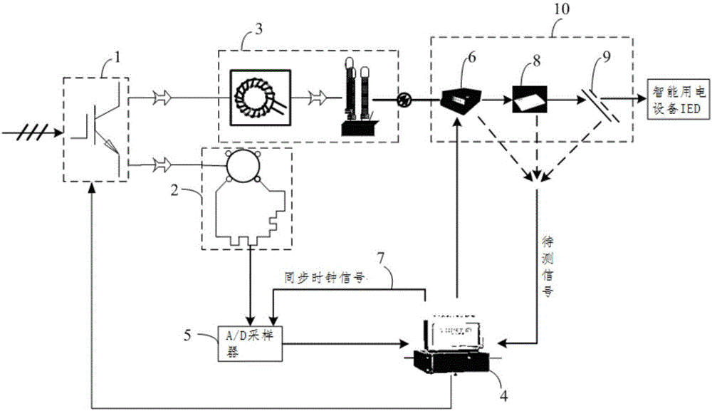
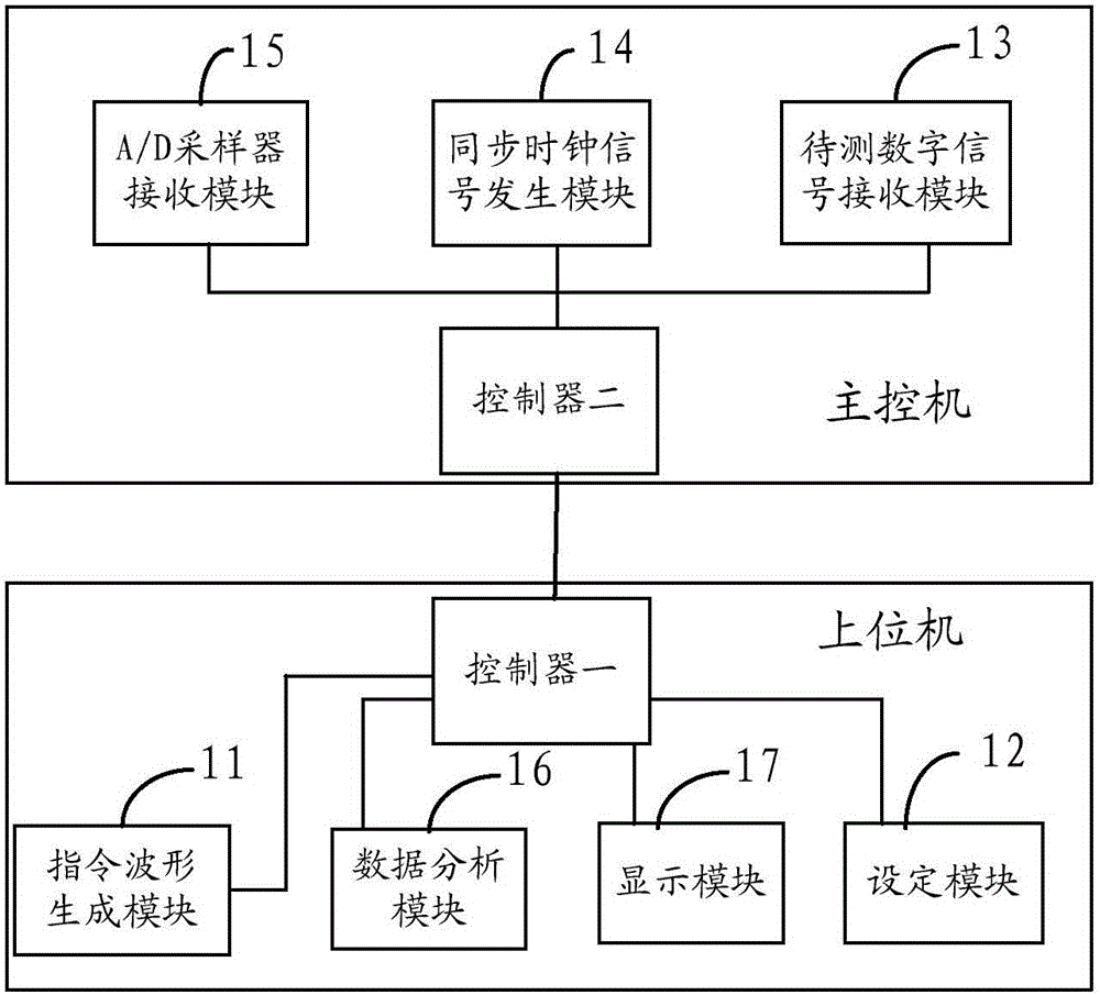
[0049] see figure 1 , the digital substation secondary signal transmission system delay characteristic testing device of the present invention comprises a three-phase controllable amplitude modulation power supply 1, a standard transformer 2, an electronic transformer 3, a control workstation 4, an A / D sampler 5, and a merging unit 6. The switch 8 and the Ethernet 9 form a digital substation secondary signal transmission system 10 . Any node of the digital substation secondary signal transmission system 10 can be used as the output terminal of the digital signal to be tested. The signal output terminals of the three-phase controllable amplitude modulation power supply 1 are respectively connected with the signal input terminals of the standard transformer 2 and the electronic transformer 3, and the sig...


PUM


Abstract

The invention provides a time-delay characteristic testing device and method of a digital substation secondary signal transmission system. The time-delay characteristic of the digital substation secondary signal transmission system, namely any node between output of a merging unit and an intelligent electric device, can be tested. According to the time-delay characteristic testing device and method, an Ethernet interface and an optical fiber interface are compatible, a time-delay test signal with periodically-changed amplitude and the stable frequency is generated through a three-phase controllable amplitude modulation power source, the cyclic wave position is calibrated through the amplitude, and interference of whole cyclic wave time delay in a time-delay test is eliminated; a self-generating synchronous clock signal is adopted, strict synchronization of inner sampling and signal circuit sampling is guaranteed, and the time-delay characteristic detecting accuracy is guaranteed; the corresponding relation between an inner sampling point and a signal circuit sampling point is determined through window comparison, the time difference of the corresponding sampling points is computed in a compared mode to obtain time-delay characteristic information, and transmission time difference shaking information of a system can be reflected.

Description

technical field [0001] The invention relates to the technical field of electric power detection, in particular to a device and method for testing delay characteristics of a secondary signal transmission system of a digital substation. Background technique [0002] Digital substation refers to the digitization of the information collection, transmission, processing and output process of the substation. The basic features are intelligent equipment, communication network, unified model and communication protocol, and automatic operation management. The analog signal of the power grid is sampled into a digital signal through the electronic transformer, and the information is summarized through the merging unit. According to the IEC61850-9-1 / 2 standard, the digital signal containing the electrical quantity is transmitted in the Ethernet frame format, through the switch and the Ethernet The network transmits information to devices such as relay protection equipment and station con...

Claims


Application Information

Patent Timeline
Patent Type & Authority Patents(China)
IPC IPC(8): G01R31/00
Inventor 陶骞高艺璇王晋崔一铂陈文游力孙建军
Owner STATE GRID CORP OF CHINA
Learn More