A kind of sand barrier sowing machine

A technology of inserting machines and sand barriers, applied in soil protection, construction, infrastructure engineering, etc., can solve the problems of unsuitable nylon sand barriers, and achieve the effects of easy implementation and promotion, labor saving, and simple structure

Inactive Publication Date: 2016-04-20
HENAN ZHONGTU IND
View PDF5 Cites 0 Cited by
  • Summary
  • Abstract
  • Description
  • Claims
  • Application Information

AI Technical Summary

Problems solved by technology

At present, some units have carried out the research and development of sand barrier laying machines, but the results of research and development are all machines specially used for laying grass grid sand barriers. These sand barrier laying machines are limited by sand barrier materials and can only be used for grass grids. The laying of sand barriers is not suitable for the laying of emerging nylon sand barriers at all

Method used


Image

  • A kind of sand barrier sowing machine
  • A kind of sand barrier sowing machine
  • A kind of sand barrier sowing machine

Examples


Embodiment 1

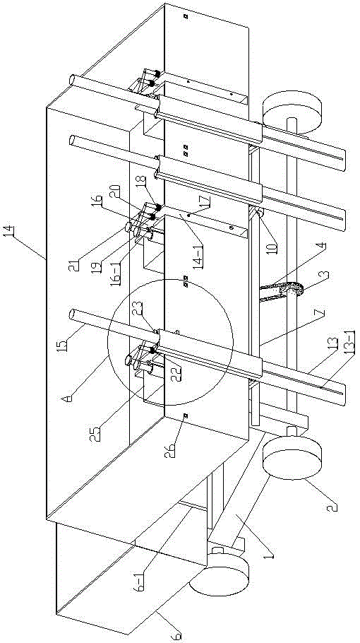
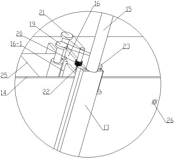
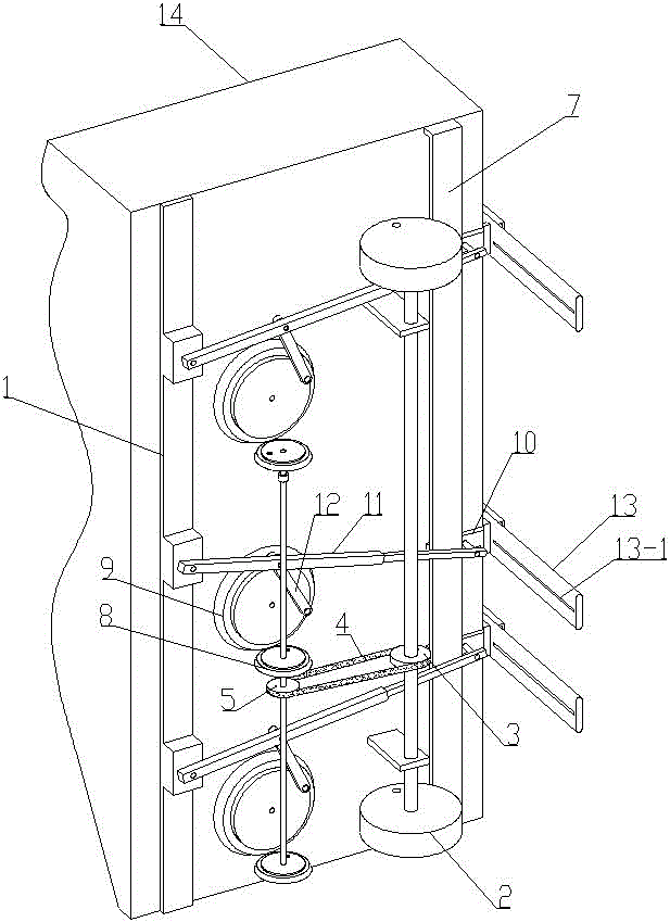
[0028] like Figure 1-5 As shown, 1. A sand barrier planting and inserting machine, comprising a frame, a walking wheel 2 arranged under the frame 1 and a tow hook (not shown in the figure) arranged at the front end of the frame 1. The frame 1 There is a power mechanism and three sowing and inserting mechanisms on it;

[0029] The power mechanism includes a driving sprocket 3 that is arranged on one side of the traveling wheel 2 and rotates coaxially with the traveling wheel 2 , and a driven sprocket 5 that is arranged below the frame 1 and linked with the driving sprocket 3 through a chain 4 . ; Described broadcasting and inserting mechanism comprises sowing guide unit and strike inserting unit; Described sowing guide unit comprises the mesh belt placement warehouse 6 that is arranged on the rack 1, the limit position that is arranged on the rack 1 behind the mesh belt placement warehouse 6 Rod 7, a small bevel gear 8 arranged on the side of the driven sprocket 5 and rotatin...

Embodiment 2

[0035] like Figure 1-5 As shown, 1. A sand barrier planting and inserting machine, comprising a frame, a walking wheel 2 arranged under the frame 1 and a tow hook (not shown in the figure) arranged at the front end of the frame 1. The frame 1 There is a power mechanism and three sowing and inserting mechanisms on it;

[0036] The power mechanism includes a driving sprocket 3 that is arranged on one side of the traveling wheel 2 and rotates coaxially with the traveling wheel 2 , and a driven sprocket 5 that is arranged below the frame 1 and linked with the driving sprocket 3 through a chain 4 . ; Described broadcasting and inserting mechanism comprises sowing guide unit and strike inserting unit; Described sowing guide unit comprises the mesh belt placement warehouse 6 that is arranged on the rack 1, the limit position that is arranged on the rack 1 behind the mesh belt placement warehouse 6 Rod 7, a small bevel gear 8 arranged on the side of the driven sprocket 5 and rotatin...


PUM


Abstract

The invention relates to a sand barrier transplanting machine which comprises a frame, travelling wheels and a drag hook. The travelling wheels are arranged below the frame, the drag hook is arranged at the front end of the frame, and a power mechanism and at least one transplanting mechanism are disposed on the frame. The power mechanism comprises a drive sprocket and a driven sprocket, wherein the drive sprocket is arranged on one side of the travelling wheel and coaxially and synchronously rotates with the travelling wheels, and the driven sprocket is disposed below the frame and in linkage with the drive sprocket through a chain. The transplanting mechanism comprises a guide unit and a hit unit. The sand barrier transplanting machine in a pull type design is free of engines and coupled at the rear end of trailer equipment when in use, the travelling wheels are driven to rotate by dragging of the trailer equipment, the travelling wheels in rotation drive the driving sprocket to rotate so as to drive the transplanting machine to run, and pavement of a sand barrier is realized. The sand barrier transplanting machine has the advantages of simple structure, reasonable design, low cost, convenience in implementation and popularization, realization of full automatic pavement of mesh sand barriers, labor saving and improvement of sand barrier pavement efficiency.

Description

technical field [0001] The invention belongs to the technical field of windbreak and sand fixation, in particular to a device for laying sand barriers, in particular to a sand barrier sowing and inserting machine. Background technique [0002] Desertification in my country is intensifying and worsening. According to the data provided by the State Forestry Administration of China, at the end of the 20th century, desertification expanded at a rate of 3,436 square kilometers every year. However, the value of use is lost, and the number of people affected by desertification in the country is 170 million. It has begun to threaten the ecological security and social and economic sustainable development of the entire northern region. The harm caused by desertification is very serious. First, under the action of strong wind and strong convection, floating dust, blowing sand and sandstorms will be formed; second, it will devour grasslands and farmland, reducing the living space of hum...

Claims


Application Information

Patent Timeline
Patent Type & Authority Patents(China)
IPC IPC(8): E02D3/00
Inventor 翟云飞杨娜张格宁翟小雯
Owner HENAN ZHONGTU IND
Why Eureka
Try Eureka