An automatic stamping machine for marking pulley assembly

An automatic stamping machine and identification tape technology, applied in the field of stamping machines, can solve the problems of unclear imprint and low efficiency, and achieve the effects of clear imprint, reduced labor intensity and simple structure

Active Publication Date: 2017-04-05
ANHUI HAOFANG ELECTROMECHANICS
View PDF9 Cites 0 Cited by
  • Summary
  • Abstract
  • Description
  • Claims
  • Application Information

AI Technical Summary

Problems solved by technology

[0003] The purpose of the present invention is to solve the problem of unclear imprint and low efficiency of stamping the product information on the pulley manually in the prior art, and to provide an automatic stamping machine for marking the pulley assembly

Method used


Image

  • An automatic stamping machine for marking pulley assembly

Examples


Embodiment Construction

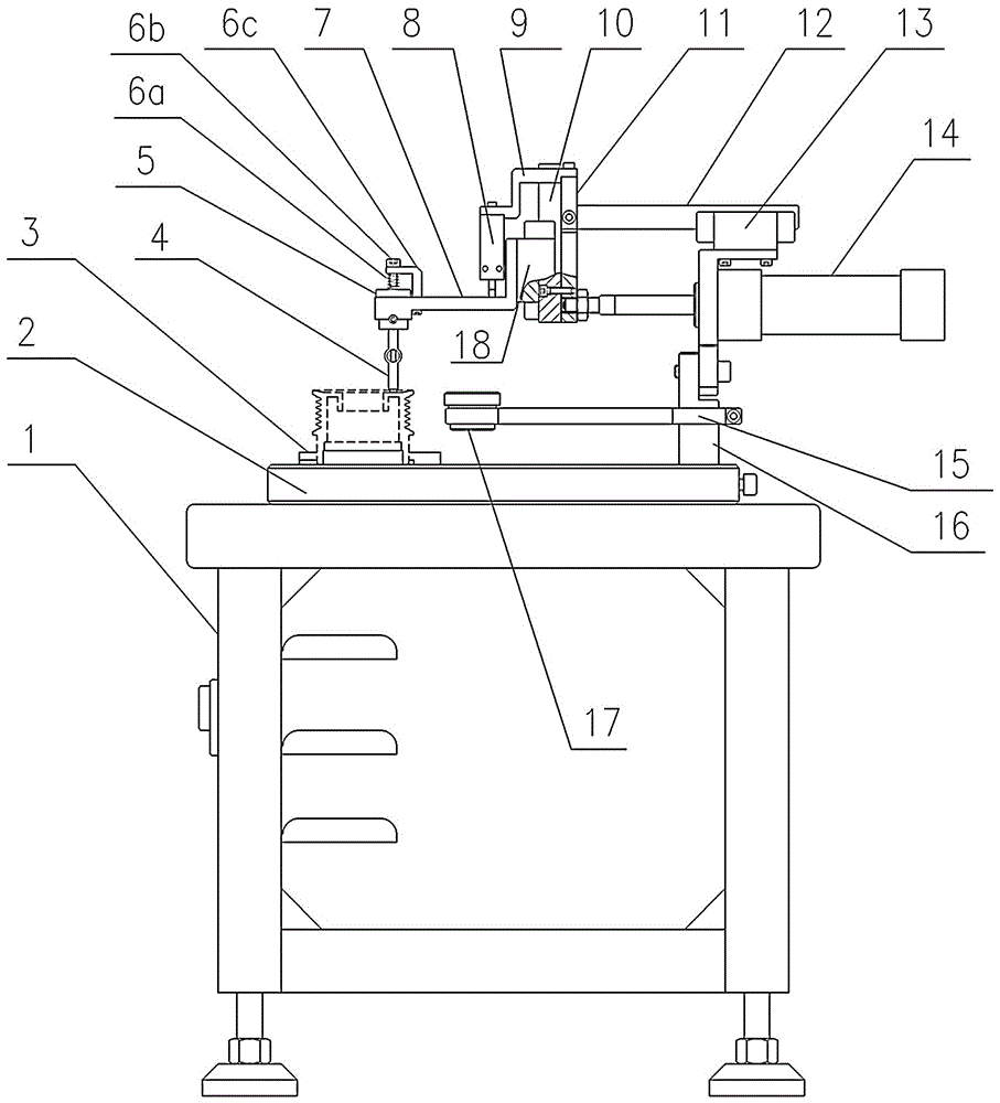
[0014] like figure 1 As shown, an automatic stamping machine for marking the pulley assembly provided by the present invention includes a workbench 1 on which a base plate 2 is provided, and a workpiece clamping seat 3 for clamping the pulley is arranged on the base plate , the substrate is also provided with a support seat 16, the middle part of the support seat is provided with an ink cartridge holder 15, and one end of the ink cartridge holder is provided with an ink cartridge 17, and the upper part of the support seat 16 is connected with a telescopic cylinder 14, and one end of the telescopic cylinder is provided with a push plate 11, A horizontal slider seat 13 is also provided above the telescopic cylinder, and a horizontal slide rail 12 is connected on the horizontal slider seat. The horizontal slide rail and the horizontal slider seat are slidably matched. Above; the upper part of the push plate is connected with a connecting plate 9, the connecting plate is provided ...


PUM


Abstract

The invention relates to an automatic stamping machine for stamping pulley assemblies. The automatic stamping machine comprises a worktable (1), a baseplate (2) is arranged on the worktable, a workpiece clamping seat (3) for clamping pulleys is arranged on the baseplate, a supporting seat (16) is further arranged on the baseplate, a telescopic cylinder (14) is connected on the supporting seat, one end of the telescopic cylinder is connected with a push plate (11), a lifting cylinder (8) is arranged on the push plate, the lower end of the lifting cylinder is connected with a pressing plate (7), a stamp seat (5) is arranged on the pressing plate, and the lower end of the stamp seat is connected with a stamp (4) aligning to the end faces of the pulleys. The automatic stamping machine has the advantages that the automatic stamping machine is simple in structure, convenient to operate and clear in stamp, labor intensity of operators is relieved, and working efficiency is improved.

Description

technical field [0001] The invention belongs to the field of stamping machines, in particular to an automatic stamping machine for marking pulley assemblies. Background technique [0002] During the production process of the pulley, it is necessary to mark the pulley to indicate the specification, batch number and other information of the pulley. The commonly used method is that the operator uses a stamp to stamp the pulley manually. The disadvantage is that the imprint of the manual marking is not clear and the efficiency is low. Contents of the invention [0003] The purpose of the present invention is to solve the problem of unclear imprint and low efficiency of stamping the product information on the pulley manually in the prior art, and to provide an automatic stamping machine for marking the pulley assembly . [0004] The purpose of the present invention is achieved through the following technical solutions: [0005] An automatic stamping machine for marking pulle...

Claims


Application Information

Patent Timeline
Patent Type & Authority Patents(China)
IPC IPC(8): B41K3/04
Inventor 闫建军李军杜朝晖杨波谢军邵波
Owner ANHUI HAOFANG ELECTROMECHANICS
Why Eureka
Try Eureka