Pneumatically rotary mechanical dismounting arm

A manipulator and cylinder technology, applied in the field of manipulators, can solve the problems of complex manipulator structure and no specific solution for pneumatic rotation.

Active Publication Date: 2014-04-30
DALIAN YUN MING AUTOMATION TECH
View PDF8 Cites 0 Cited by
  • Summary
  • Abstract
  • Description
  • Claims
  • Application Information

AI Technical Summary

Problems solved by technology

[0002] The manipulator is an indispensable equipment in modern disassembly and assembly operations, but the existing manipulator structure is too complicated, and there is no specific solution to the problem of pneumatic rotation

Method used


Image

  • Pneumatically rotary mechanical dismounting arm
  • Pneumatically rotary mechanical dismounting arm

Examples


Embodiment Construction

[0013] The present invention will be further described below in conjunction with the accompanying drawings.

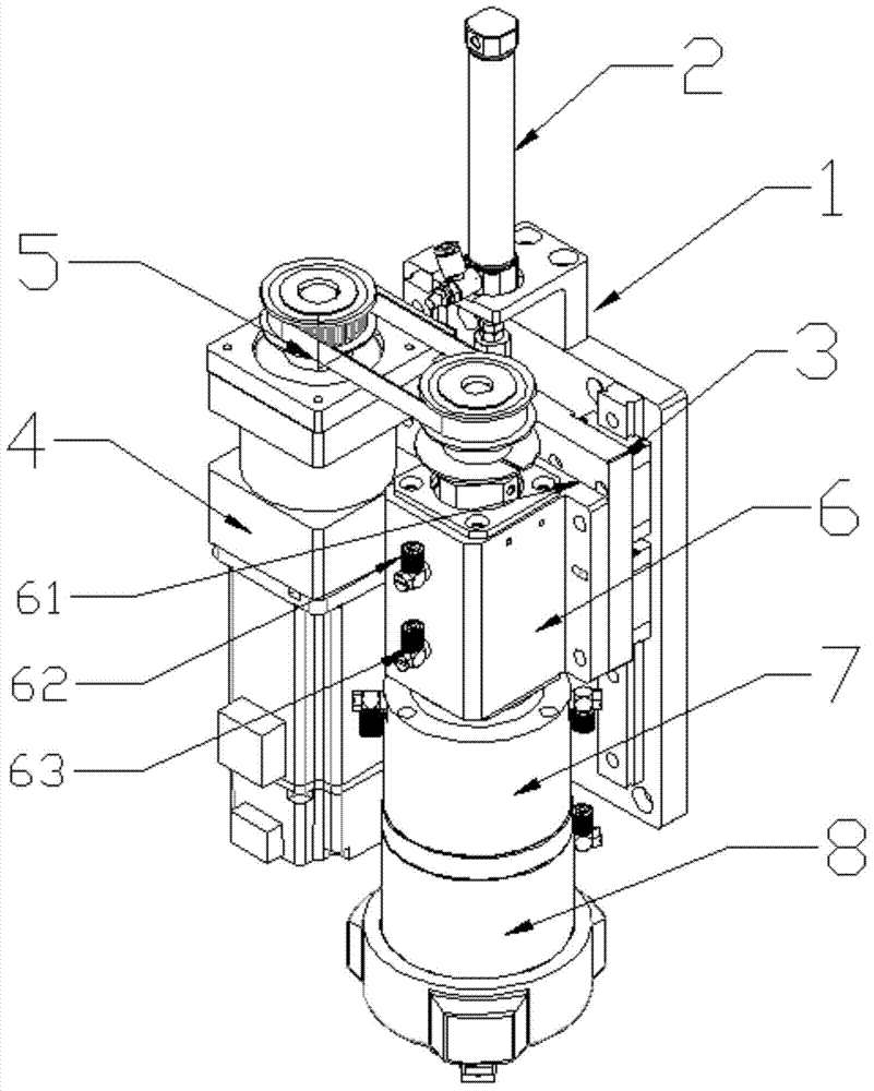
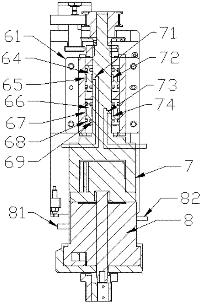
[0014] like figure 1 , figure 2 As shown, a pneumatic rotary disassembly manipulator includes a cylinder mounting plate 1, a cylinder 2 is installed on the top of the cylinder mounting plate 1, and the cylinder 2 is connected to a sliding plate 3 that can be slidably arranged on the cylinder mounting plate. The servo motor 4, the servo motor 4 drives the rotary shaft 7 passing through the bearing through the rotary air supply part 6 through the transmission belt 5, the rotary shaft 7 is connected to the air claw 8, and the rotary air supply part 6 includes a fixed part arranged on the sliding plate 3 Seat 61, said fixed seat 61 is provided with air inlet and outlet one 62 and air inlet and outlet two 63, and air inlet and outlet one 62 communicates with the upper outer seal chamber 65 of upper bearing washer 64, and air inlet and outlet two 63 communicates with the l...


PUM


Abstract

The invention discloses a pneumatically rotary mechanical dismounting arm, comprising an cylinder mounting plate, wherein the top end of the cylinder mounting plate is provided with a cylinder, the cylinder is connected with a sliding plate which is arranged on the cylinder mounting plate in a sliding manner, a servo motor is mounted on the sliding plate, the servo motor drives a rotary shaft through a driving belt and the rotating shaft penetrates a rotary air supply part, and the rotary shaft is connected with a pneumatic claw. The pneumatically rotary mechanical dismounting arm has the advantages that the driving part adopts the servo motor as a power source which can rapidly drives the pneumatic claw to do rotary motion and can accurately control the gyroscopic moment of the pneumatic claw, so that the work efficiency is high; the transmission part adopts a synchronous belt for driving, so that the torque transmission is stable, and the noise is low; the rotary air supply part adopts the manner of machining vent holes in the rotary shaft and matching with a sealing structure, so that the purpose of rotary air supplying is achieved, and the assembling efficiency is high.

Description

technical field [0001] The invention relates to the technical field of manipulators, in particular to a pneumatic rotary disassembly manipulator. Background technique [0002] The manipulator is an indispensable equipment in modern disassembly and assembly operations, but the existing manipulator structure is too complicated, and there is no specific solution to the problem of pneumatic rotation. Contents of the invention [0003] The object of the present invention is to provide a pneumatic rotary disassembly manipulator aiming at the defects and deficiencies of the prior art. [0004] In order to achieve the above object, the technical scheme adopted in the present invention is: [0005] A pneumatic rotary disassembly manipulator according to the present invention includes a cylinder mounting plate, a cylinder is installed on the top of the cylinder mounting plate, the cylinder is connected to a sliding plate that can be slidably arranged on the cylinder mounting plate,...

Claims


Application Information

Patent Timeline
Patent Type & Authority Applications(China)
IPC IPC(8): B23P19/04
CPCB23P19/04
Inventor 王贵松李雪李明翔
Owner DALIAN YUN MING AUTOMATION TECH
Why Eureka
Try Eureka