
Linear reciprocating motor

A linear reciprocating, motor stator technology, applied in the direction of electrical components, electromechanical devices, electric components, etc., can solve the problems of reduced mechanical efficiency, high production costs, and many transmission links, so as to improve mechanical efficiency, reduce production costs, and reduce transmission link effect

Inactive Publication Date: 2014-04-09
刘开超
View PDF5 Cites 30 Cited by
  • Summary
  • Abstract
  • Description
  • Claims
  • Application Information

AI Technical Summary

Problems solved by technology

[0002] Traditional motors generally adopt transmission methods such as belts and gears, and there are many transmission links, resulting in a decrease in mechanical efficiency, and traditional motors cannot achieve reciprocating motion. To achieve reciprocating motion, the cam must be driven to achieve reciprocating motion. Many damaged parts, high production cost, large volume, difficult to install
[0003] In addition, the existing diaphragm pump realizes the reciprocating motion of the piston through air or cam, so the efficiency is low

Method used


Image

  • Linear reciprocating motor
  • Linear reciprocating motor
  • Linear reciprocating motor

Examples


Embodiment Construction

[0018] The present invention is described in further detail below in conjunction with accompanying drawing:

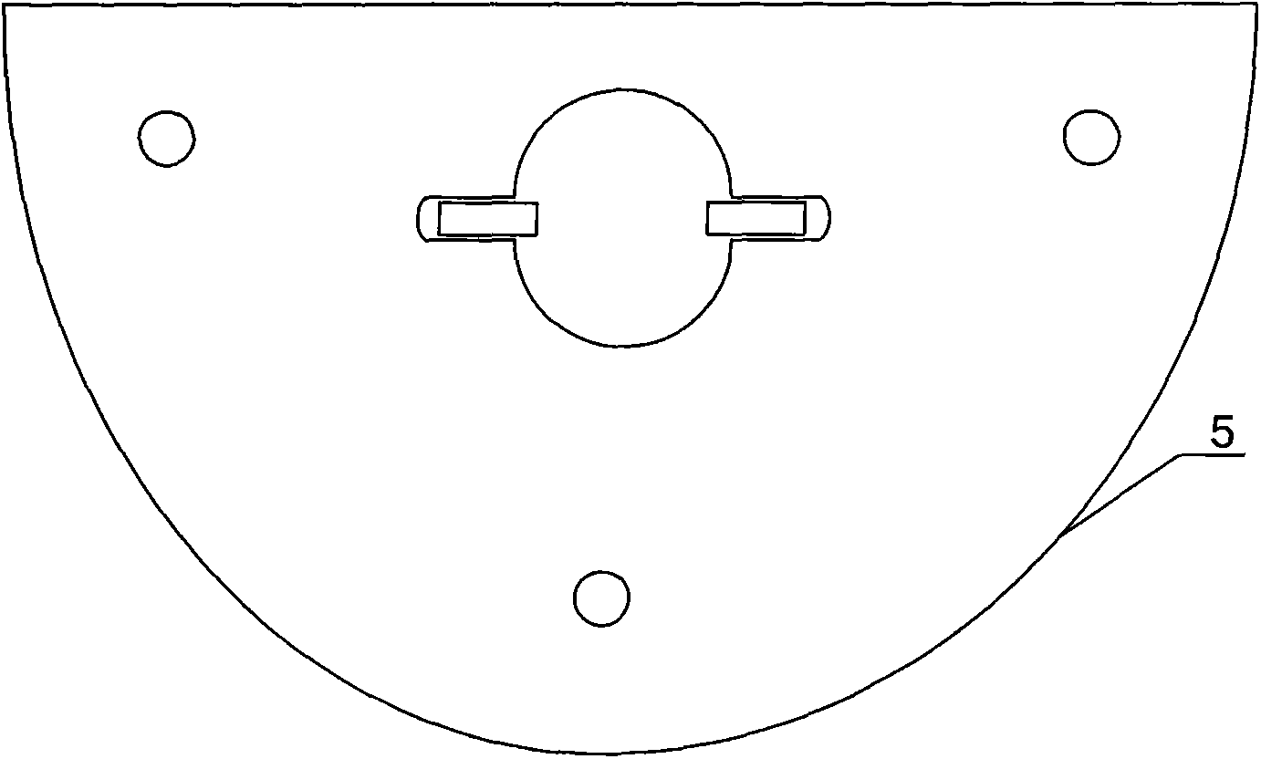
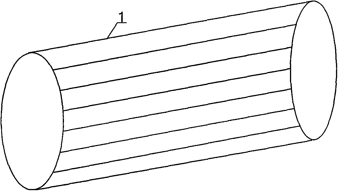
[0019] see Figure 1 to Figure 6 , a linear reciprocating motor, including a reciprocating screw rod 4, the reciprocating screw rod 4 is covered with a hollow shaft 2 with a circular hole in the side wall, and the guide block 3 is placed in the circular small hole of the hollow shaft and connected with the reciprocating wire The two-way chute of the rod 4 is in contact, and the outer side of the hollow shaft 2 on which the guide block 3 is installed is covered with a rotor 1, and the rotor 1 is covered with a motor stator.

[0020] see Figure 4 The guide block 3 includes a guide handle with a round top and a guide slider arranged below the guide handle, and the shape of the contact end of the guide slider and the two-way chute of the reciprocating screw rod 1 is crescent-shaped.

[0021] The sidewalls at the two ends of the reciprocating screw mandrel 4 are symmetri...


PUM


Abstract

The invention discloses a linear reciprocating motor. The linear reciprocating motor comprises a reciprocating screw rod (4) which is sleeved with a hollow shaft (2), a small round hole is formed in the side wall of the hollow shaft (2), a guide block (3) is placed in the small round hole of the hollow shaft and makes contact with a bidirectional sliding groove of the reciprocating screw rod (4), the hollow shaft (2) provided with the guide block (3) is sleeved with a rotor (1), and the rotor (1) is sleeved with a motor stator. According to the linear reciprocating motor, the guide block is arranged in the small round hole in the hollow shaft arranged outside the reciprocating screw rod in a sleeved mode, then the rotor is arranged uniformly, and after installation is finished, the hollow shaft rotates to drive the guide block to move in the reciprocating screw rod so that front and back linear reciprocating motion of the reciprocating screw rod can be achieved under the action of the guide block. Thus, the linear reciprocating motor can be applied to various occasions needing the reciprocating motion, the number of transmission links is reduced, mechanical efficiency is improved, production cost is reduced, and the linear reciprocating motor is simplified substantially.

Description

technical field [0001] The invention belongs to the technical field of motors, and relates to a linear reciprocating motor. Background technique [0002] Traditional motors generally adopt transmission methods such as belts and gears, and there are many transmission links, resulting in a decrease in mechanical efficiency, and traditional motors cannot achieve reciprocating motion. To achieve reciprocating motion, the cam must be driven to achieve reciprocating motion. There are many damaged parts, the production cost is high, the volume is large, and it is difficult to install. [0003] In addition, the existing diaphragm pump realizes the reciprocating motion of the piston through air or cam, so the efficiency is low. Contents of the invention [0004] In order to solve the above technical problems, the present invention provides a linear reciprocating motor with few transmission links and high mechanical efficiency. [0005] The present invention is achieved through th...

Claims


Application Information

Patent Timeline
Patent Type & Authority Applications(China)
IPC IPC(8): H02K41/02
Inventor 刘开超
Owner 刘开超
Learn More