
Surgical anchor delivery system

A transmission system and surgical technology, applied in the direction of surgery, surgical instruments, fixers, etc., can solve the problems of high cost and low efficiency

Active Publication Date: 2014-04-02
SMITH & NEPHEW INC
View PDF8 Cites 11 Cited by
  • Summary
  • Abstract
  • Description
  • Claims
  • Application Information

AI Technical Summary

Problems solved by technology

However, this is both inefficient and expensive from a procedural standpoint, as with most anchor delivery systems, most of the cost is attributable to the disposable delivery device rather than the cost of the anchor itself

Method used


Image

  • Surgical anchor delivery system
  • Surgical anchor delivery system
  • Surgical anchor delivery system

Examples


Embodiment Construction

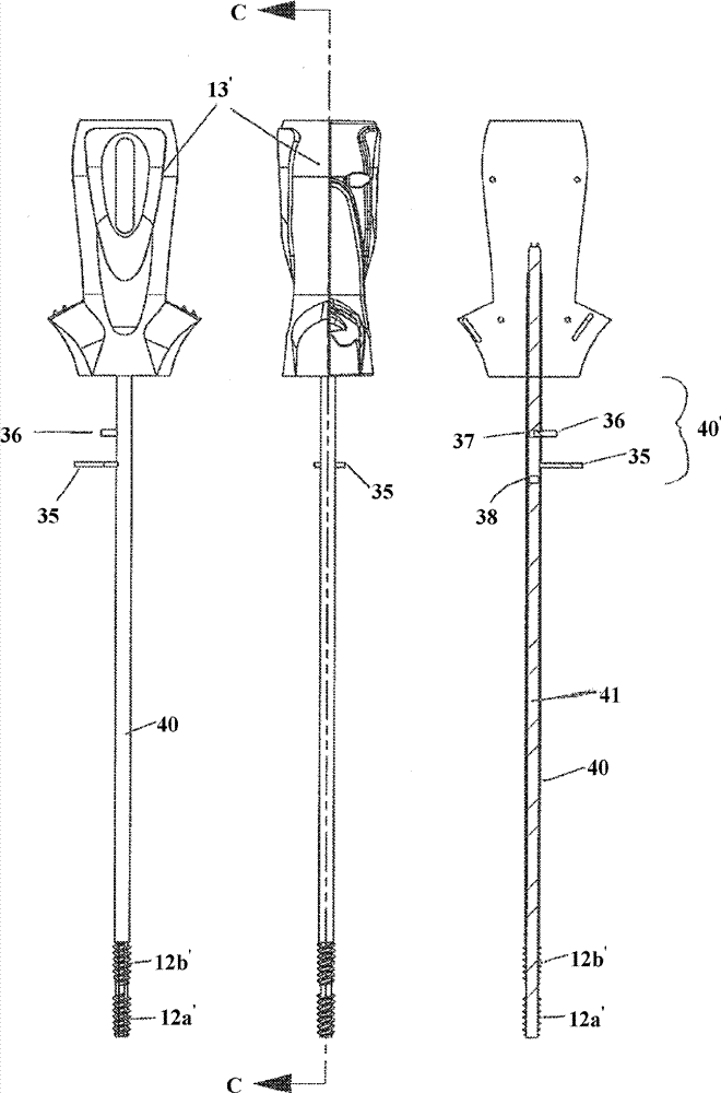
[0031] see figure 1 , shows a surgical anchor delivery system 10 formed from a delivery device 11 and two or more surgical anchors in the form of suture anchors 12 . The delivery device 11 comprises a proximal handle 13 having a shaft 14 extending therefrom, two suture anchors 12 mounted serially at the distal end of the shaft 14, and a mechanism for advancing the anchors distally. 15.

[0032] The mechanism 15 is formed by a sleeve 20 and a driver 21 . Sleeve 20 is slidably mounted on shaft 14 and has a distal end that abuts the proximal-most surgical anchor. The driver 21 is formed with the handle 13 and is rotatably mounted on the shaft 14 and is actuatable in use to advance the sleeve 20 distally, once the most distal anchor has been deployed, the proximal most The anchor moves into position suitable for deployment. see below Figure 4 This process is described in more detail through FIG. 6 .

[0033] exist figure 1, and in other figures illustrating the invention, ...


PUM


Abstract

The present invention relates to a surgical anchor delivery system (10) including a delivery device (11) having a shaft (14) and a handle (13), an advancer (15) for advancing a surgical anchor (12) distally along the shaft (14); and a plurality of surgical anchors (12) loaded upon the shaft (14).

Description

technical field [0001] The present invention relates to surgical instruments, and more particularly, to surgical instruments for delivering surgical anchors. Background technique [0002] Surgical anchors are typically supplied with single-use, disposable delivery devices, wherein each anchor delivery system includes a delivery device preloaded with a single anchor. Typically, a surgical procedure will involve the use of two or more surgical anchors, requiring the use of several delivery devices. However, this is both inefficient and expensive from a procedural standpoint, since with most anchor delivery systems, most of the cost is attributable to the disposable delivery device rather than the cost of the anchor itself. Therefore, a more cost-effective and procedurally efficient approach is desirable. Contents of the invention [0003] In its broadest sense, the present invention provides a surgical anchor delivery system comprising a delivery device having an elongated...

Claims


Application Information

Patent Timeline
IPC IPC(8): A61B17/04
CPCA61B17/888A61B17/0483A61B2017/0441A61B17/0401A61B2017/0409A61B17/04A61B17/10A61B17/11
Inventor M.E.豪斯曼
Owner SMITH & NEPHEW INC
Learn More