
A fiber grating strain sensor and its installation method

A technology of strain sensor and fiber grating, which is applied in the direction of using optical devices, instruments, measuring devices, etc., can solve the problems of low sensitivity and poor sensitivity consistency of fiber grating strain sensors, and achieve material consistency and low processing accuracy requirements, and practicality Strong, easy-to-achieve effects

Active Publication Date: 2016-06-01
BEIJING AEROSPACE TIMES OPTICAL ELECTRONICS TECH
View PDF8 Cites 0 Cited by
  • Summary
  • Abstract
  • Description
  • Claims
  • Application Information

AI Technical Summary

Problems solved by technology

When the fiber grating strain sensor structure with preloaded tensile strain is used, the packaging structure itself has a reinforcing effect on the fiber grating, which leads to a decrease in sensitivity and poor sensitivity consistency of the fiber grating strain sensor

Method used


Image

  • A fiber grating strain sensor and its installation method
  • A fiber grating strain sensor and its installation method
  • A fiber grating strain sensor and its installation method

Examples


Embodiment Construction

[0029] Below in conjunction with accompanying drawing and specific embodiment the present invention is described in further detail:

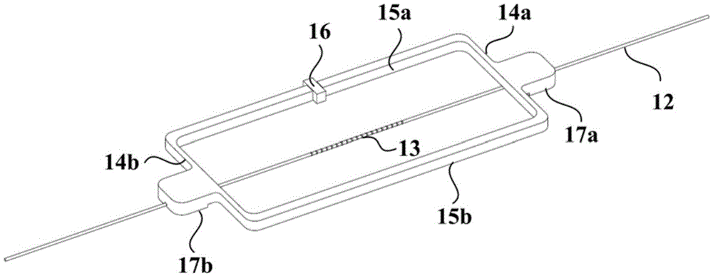
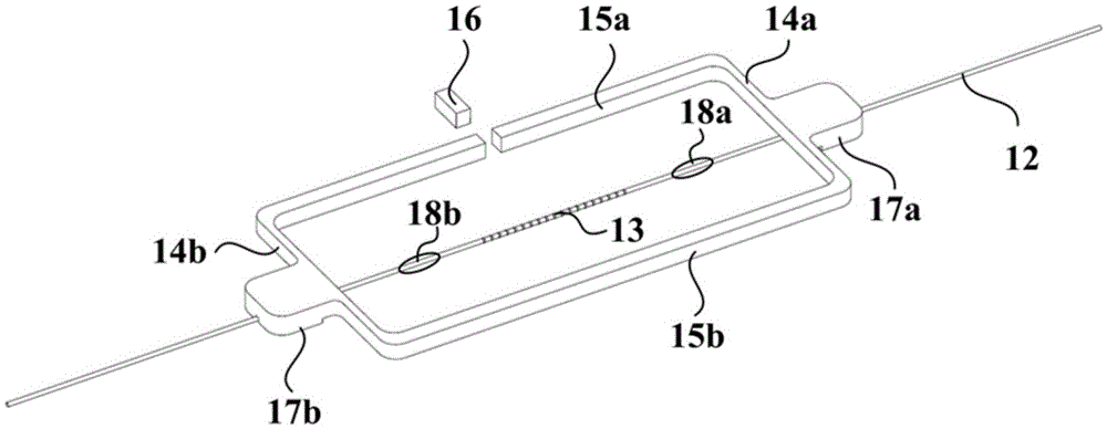
[0030] Such as figure 2 Shown is a schematic structural view of the fiber grating strain sensor of the present invention during the packaging process and before installation and use. The fiber grating strain sensor of the present invention includes a first high elastic beam 14a, a second high elastic beam 14b, a first support column 15a, a second support Column 15b, first installation base 17a, second installation base 17b, baffle 16 and fiber grating 13, wherein first high elastic beam 14a, first support column 15a, second high elastic beam 14b and second support column 15b in sequence The connection forms a box structure, and the four corners of the formed box structure can be rounded or right-angled.

[0031] The first installation base 17a is connected to the first high elastic beam 14a, the second installation base 17b is connected to the...


PUM


Abstract

The invention relates to an optical fiber grating strain sensor and an installation method thereof. The optical fiber grating strain sensor comprises high-elasticity beams, supporting columns, a stopping piece, installation substrates and an optical fiber grating. When the optical fiber grating strain sensor is packed, the supporting columns and the stopping piece provide supporting force for optical fiber grating pre-loaded tension strain. The installation method of the optical fiber grating strain sensor includes the steps that the installation substrates are pasted to or welded to the surface of a to-be-tested structure, or optical fibers in the high-elasticity beams at two ends of the optical fiber grating are connected to the surface of the to-be-tested structure in an adhesive mode, and then the stopping piece is removed. According to the structure and the installation method of the optical fiber grating strain sensor, the supporting force is provided for the optical fiber grating pre-loaded tension strain through the supporting columns and the stopping piece, requirements for consistency of materials of the structure and machining accuracy are low, and due to the fact that the stopping piece is removed, the optical fiber grating strain sensor has good strain sensitivity and sensitivity consistency.

Description

technical field [0001] The invention belongs to the technical field of optical fiber sensing, and in particular relates to an optical fiber grating strain sensor and an installation method thereof. Background technique [0002] The fiber Bragg grating strain sensor uses the linear relationship between the center wavelength of the fiber Bragg grating reflection spectrum and the strain on the fiber Bragg grating to measure. It has become an important means of structural testing and structural health monitoring. [0003] Fiber Bragg gratings are easy to be subjected to tensile strain, not easy to be applied to compressive strain, and the reflection spectrum of the grating region is prone to chirping under the action of uneven strain; Reflection spectrum chirp and other targeted structure and installation method design. [0004] An existing FBG strain sensor structure and installation method that can simultaneously measure tension / compression strain is shown in the patent "WO2...

Claims


Application Information

Patent Timeline
Patent Type & Authority Patents(China)
IPC IPC(8): G01B11/16
Inventor 唐才杰崔留住王学锋
Owner BEIJING AEROSPACE TIMES OPTICAL ELECTRONICS TECH
Learn More