
Automotive radar sensor installation support

A technology for mounting brackets and automotive radar, applied in vehicle components, transportation and packaging, etc., can solve the problems of inflexible wiring harnesses, increased difficulty in operation and installation, and increased manufacturing costs, achieving flexible installation methods, avoiding quality hazards, and simple assembly Effect

Inactive Publication Date: 2014-03-26
SHENZHEN LONGHORN AUTOMOTIVE ELECTRONICS EQUIPCO
View PDF6 Cites 14 Cited by
  • Summary
  • Abstract
  • Description
  • Claims
  • Application Information

AI Technical Summary

Problems solved by technology

[0003] Nowadays, the safety of the automobile industry is getting more and more attention. The number of reversing radar sensors used in a car is usually 2, 3, 4, 6, 8, 12, etc. In order to make a reversing radar sensor In the matching installation of various models, it is usually chosen to use a bracket to fix the reversing radar sensor on the bumper. However, each mounting bracket can only install the reversing radar sensor in a specific direction, and the reversing radar sensor is usually installed in a central plane. , so often need 2, 3, 4, or even 6 types of brackets to match, which not only results in a large number of bracket molds, but also directly increases the manufacturing cost; and in the installation process, because the appearance of various brackets is very similar, it is easy to appear confusion. In addition, due to the limitation of the possible area in the assembly process, it will make the operation and installation more difficult, and it may also increase the length of the used wire harness and increase the difficulty of fixing the wire harness. Not flexible enough, etc.

Method used


Image

  • Automotive radar sensor installation support
  • Automotive radar sensor installation support
  • Automotive radar sensor installation support

Examples


Embodiment Construction

[0012] In order to make the object, technical solution and advantages of the present invention clearer, the present invention will be further described in detail below in conjunction with the accompanying drawings and embodiments.

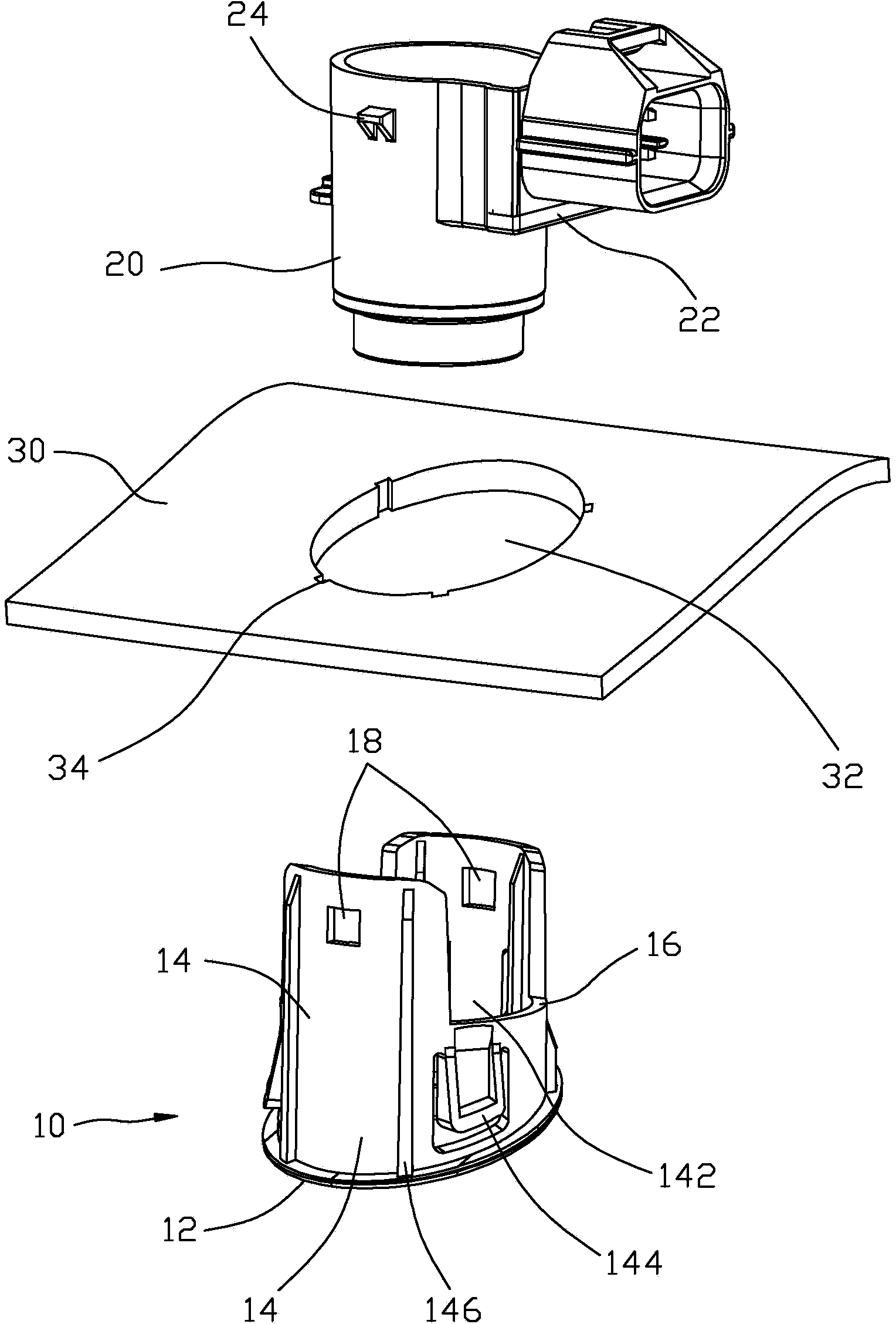
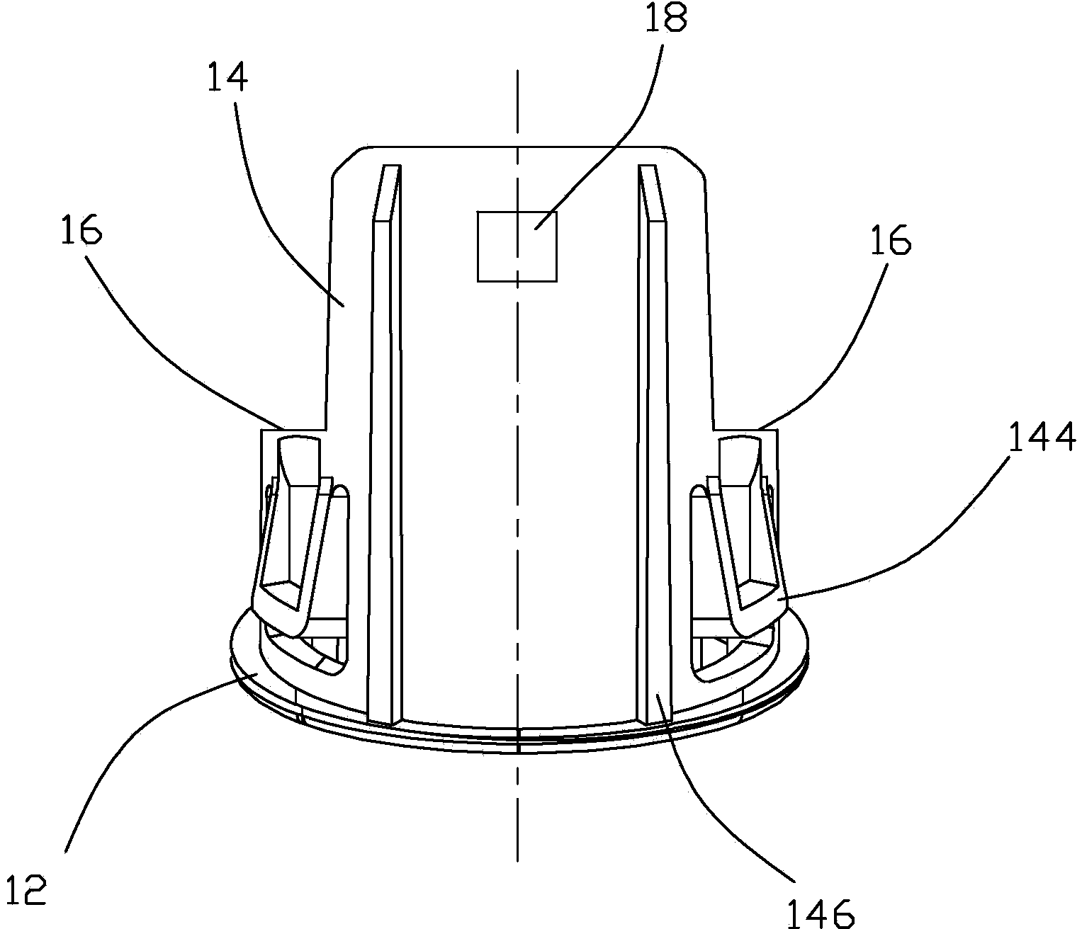
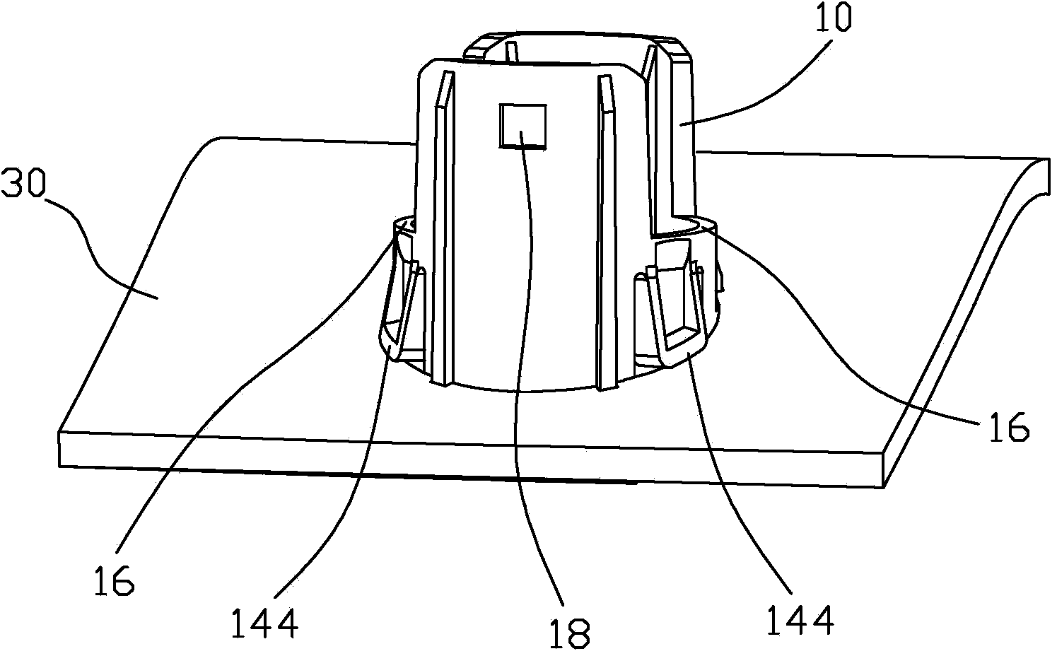
[0013] Such as figure 1 As shown, the mounting bracket 10 of the automotive radar sensor 20 of the present invention is used to fix the reversing radar sensor 20 on the bumper 30, and the bumper 30 is formed with a mounting hole 32 for passing through the mounting bracket 10. The mounting hole A plurality of limiting grooves 34 are formed on the edge of the mounting hole 32 . The limiting grooves 34 are arranged at intervals along the circumferential direction of the mounting hole 32 and communicate with the mounting hole 32 . A positioning step 22 is formed on the outer surface of the sensor 20 for positioning with the mounting bracket 10. In addition, two lugs 24 are formed on the outer surface of the sensor 20 for snapping and fixing with the mo...


PUM


Abstract

An automotive radar sensor installation support is used for fixing a sensor on a bumper. The automotive radar sensor installation support comprises a base and a fixing base, wherein the base extends to form the fixing base, the outer diameter of the fixing base is smaller than that of the base, a containing space used for containing the sensor is formed in the fixing base, two clamping grooves and two buckling holes are formed in the fixing base, the two clamping grooves are symmetrically formed, the two buckling holes are symmetrically formed, the two clamping grooves are used for locating the sensor in a matched mode, and the two buckling holes are used for fixing the sensor in a buckling mode. Therefore, a locating step of the sensor can be flush with any one groove to be inserted into the fixing base, the sensor is arranged on two sides of the central surface at a symmetrical angle, the installation type is more flexible, and the automotive radar sensor installation support is particularly suitable for the area where the assembly space is small to cause installation difficulty. In addition, species of installation supports can be fewer, one installation support is shared by the whole automobile, cost is lower, and quality hidden danger caused by multiple species of installation supports is also avoided.

Description

technical field [0001] The invention relates to auto parts, in particular to a mounting bracket for an automotive radar sensor. Background technique [0002] At present, the proportion of reversing radar sensors used in cars is increasing. It is generally installed on the bumper at the front or rear of the car to detect the distance between the car body and obstacles and transmit it to the display screen in front of the driver's seat. It can be displayed on the display or prompt the driver through the buzzer or the sound alarm mode of the instrument panel, so that the driver can grasp the front and rear conditions of the car and avoid collision between the car body and obstacles when reversing. [0003] Nowadays, the safety of the automobile industry is getting more and more attention. The number of reversing radar sensors used in a car is usually 2, 3, 4, 6, 8, 12, etc. In order to make a reversing radar sensor In the matching installation of various models, it is usually ...

Claims


Application Information

Patent Timeline
IPC IPC(8): B60R11/00
Inventor 麦福利彭炳炎包青成
Owner SHENZHEN LONGHORN AUTOMOTIVE ELECTRONICS EQUIPCO
Learn More