
Wafer chip jacking mechanism

A technology for jacking up mechanisms and chips, which is applied in the fields of electrical components, semiconductor/solid-state device manufacturing, circuits, etc., and can solve problems such as difficult replacement and complicated jacking mechanisms

Active Publication Date: 2014-03-12
CHINA ELECTRONIC TECH GRP CORP NO 2 RES INST
View PDF3 Cites 9 Cited by
  • Summary
  • Abstract
  • Description
  • Claims
  • Application Information

AI Technical Summary

Problems solved by technology

[0003] The invention provides a wafer chip jacking mechanism, which solves the technical problem that the jacking mechanism in the existing wafer chip jacking mechanism is complicated and difficult to replace

Method used


Image

  • Wafer chip jacking mechanism
  • Wafer chip jacking mechanism
  • Wafer chip jacking mechanism

Examples


Embodiment Construction

[0013] The present invention is described in detail below in conjunction with accompanying drawing:

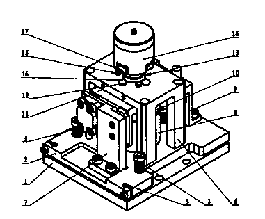
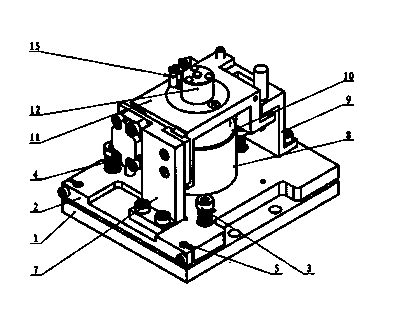
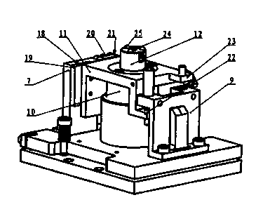
[0014] A wafer chip jacking mechanism, comprising a mechanism base plate 1, a motor stator fixing plate 2 is arranged on the mechanism base plate 1, a voice coil motor stator 8 is fixedly arranged on the motor stator fixing plate 2, and a voice coil motor stator 8 is fixed on the motor stator fixing plate 2 The motor stator fixed plate 2 on one side is provided with a reading head installation frame 7, and the motor stator fixed plate 2 on the other side of the voice coil motor stator 8 is provided with a Z-shaped limit frame 9, and in the voice coil motor stator 8 A voice coil motor mover 10 that can be lifted up and down is provided, an inverted L-shaped lifting plate 11 is provided on the top of the voice coil motor mover 10, and lifting guide rail grooves 19 are respectively provided on the inner side of the reading head mounting frame 7 and the grating ruler reading head ...


PUM


Abstract

The invention discloses a wafer chip jacking mechanism. By the aid of the wafer chip jacking mechanism, the problem of difficulty in replacing ejector pins in existing wafer chip stripping mechanisms can be solved. The wafer chip jacking mechanism comprises a motor stator fixing plate (2). A voice coil motor stator (8) is fixedly arranged on the motor stator fixing plate (2), an inverted-L-shaped lifting plate (11) is arranged on the top of a voice coil motor rotor (10), a lifting guide rail groove (19) is formed in the inner side surface of a reading head mounting frame (7), a grating scale reading head (20) is arranged on the inner side surface of the reading head mounting frame (7), a lifting slider (18) and a grating scale (21) are respectively arranged on the outer side of an upright plate of the inverted-L-shaped lifting plate (11), a lifting cylinder (12) is arranged on the top surface of a horizontal plate of the inverted-L-shaped lifting plate (11), pull-in magnets (15) of an ejector pin actuator (14) are respectively arranged on the outer side of a through hole (13), and an ejector pin mounting seat pull-in magnet (24) and three ejector pin mounting seat support balls (25) are respectively arranged on the top surface of the lifting cylinder (12). The wafer chip jacking mechanism is applicable to wafer chip stripping mechanisms with the requirement of frequently replacing wafer chips with different sizes.

Description

technical field [0001] The invention relates to a wafer chip jacking mechanism, in particular to a chip jacking mechanism applied to a chip multifunctional precision assembly machine for jacking up a chip from a wafer. Background technique [0002] The wafer chip jacking mechanism is a key component used in the multi-functional precision assembly machine. It is used to complete the chip jacking work from the wafer, and cooperates with the chip picking robot of the equipment to complete the process of picking up the chip from the wafer. The structure of the existing wafer jacking mechanism is complicated, and the thimble needs to be replaced when jacking up chips of different specifications, which is time-consuming and laborious. In addition, there are also problems that the jacking height of the thimble is difficult to adjust and the jacking force cannot be adjusted as needed. Contents of the invention [0003] The invention provides a wafer chip jacking mechanism, which s...

Claims


Application Information

Patent Timeline
IPC IPC(8): H01L21/687
CPCH01L21/68742
Inventor 张志耀曹国斌霍灼琴田志峰王晓奎
Owner CHINA ELECTRONIC TECH GRP CORP NO 2 RES INST
Learn More