Ferrite attaching jig

A technology for combining fixtures and ferrite, which is applied in the field of ferrite lamination of flexible circuit boards, can solve the problems of poor ferrite rework, slow ferrite lamination speed, and partial lamination defects, so as to improve lamination efficiency and solve Poor sticking problem, simple structure effect

Inactive Publication Date: 2014-02-12
江苏迅维电子科技有限公司
View PDF0 Cites 2 Cited by
  • Summary
  • Abstract
  • Description
  • Claims
  • Application Information

AI Technical Summary

Problems solved by technology

[0002] At present, in the bonding process of flexible circuit boards, due to the limitation of the ferrite material, the industry generally adopts a single PCS bonding process, and the single PCS ferrite bonding speed is slow, and there are defects of bonding deviation, and the ferrite bonding is biased. Poor post-rework

Method used


Image

  • Ferrite attaching jig

Examples


Embodiment Construction

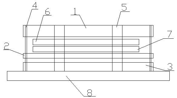
[0010] A ferrite bonding jig, comprising a cover plate 1, a take-off plate 2 and a bottom plate 3 arranged parallel to each other, the take-off plate 2 is arranged between the bottom plate 3 and the cover plate 1, and vertical The positioning pin 4 arranged, the middle part of the base plate 3 is provided with a positioning block 5, and the taking plate 2 and the cover plate 1 are respectively provided with a positioning hole I and a positioning hole II cooperating with the positioning pin 4 and the positioning block 5. The positioning pin 4 is inserted in the positioning hole I, and the positioning block 5 is inserted in the positioning hole II; the lower end of the bottom plate 3 is provided with a supporting plate 8 riveted therewith.


PUM


Abstract

The invention relates to a ferrite attaching jig which comprises a cover plate, a taking plate and a base plate which are parallel to one another. The taking plate is arranged between the base plate and the cover plate, positioning pins are vertically arranged around the base plate, positioning blocks are arranged in the middle of the base plate, the taking plate and the cover plate are respectively provided with a positioning hole I and a positioning hole II which are matched with the positioning pins and the positioning blocks, the positioning pins are arranged in the positioning holes I in a penetrating mode, and the positioning blocks are arranged in the positioning holes II in a penetrating mode. The ferrite attaching jig is simple in structure, effectively improves attaching efficiency and solves the problems that manual attaching is offset and bad.

Description

technical field [0001] The invention relates to a ferrite bonding jig, which belongs to the technical field of flexible circuit board ferrite bonding. Background technique [0002] At present, in the bonding process of flexible circuit boards, due to the limitation of the ferrite material, the industry generally adopts a single PCS bonding process, and the single PCS ferrite bonding speed is slow, and there are defects of bonding deviation, and the ferrite bonding is biased. Poor reworkability. Contents of the invention [0003] In view of the above defects, the object of the present invention is to provide a ferrite lamination jig with simple structure, high lamination efficiency and high lamination yield. [0004] For this reason the technical solution that the present invention adopts is: comprise the cover plate that arranges in parallel with each other, get plate and base plate, described get plate is arranged between base plate and cover plate, be provided with vert...

Claims


Application Information

Patent Timeline
Patent Type & Authority Applications(China)
IPC IPC(8): H05K3/30
Inventor 仲伟荣
Owner 江苏迅维电子科技有限公司
Why Eureka
Try Eureka