Bending device and component mounting device

A technology of a bending device and an installation device, applied in the field of bending, can solve the problems of insufficient lead bending, improper contact between the lead and the bending device, and inability to install lead components reliably.

Active Publication Date: 2016-06-15
YAMAHA MOTOR CO LTD
View PDF7 Cites 0 Cited by
  • Summary
  • Abstract
  • Description
  • Claims
  • Application Information

AI Technical Summary

Problems solved by technology

[0003] As in the above-mentioned bending mechanism, in the structure in which the lead wire inserted into the insertion hole is brought into contact with the bending device (bending unit) provided for the insertion hole to bend the lead wire, when the positional relationship between the insertion hole and the bending device When it is inappropriate, sometimes the contact between the lead wire and the bending device is not proper and the bending of the lead wire is insufficient.
Insufficient bending of the leads may result in the lead components not being reliably mounted on the board

Method used


Image

  • Bending device and component mounting device
  • Bending device and component mounting device
  • Bending device and component mounting device

Examples


Embodiment Construction

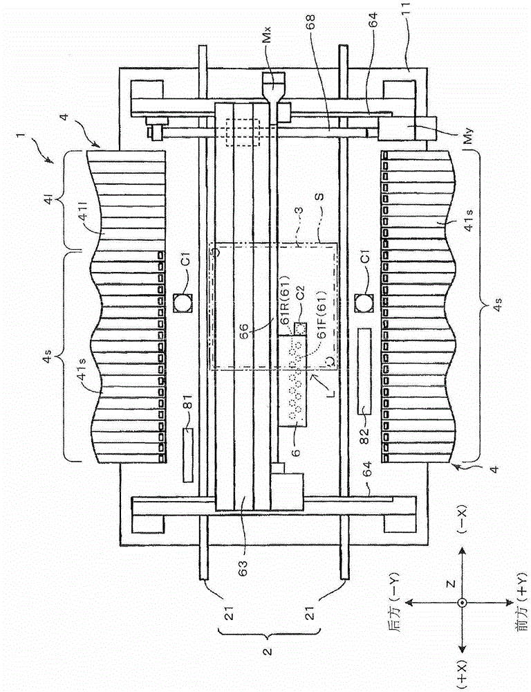
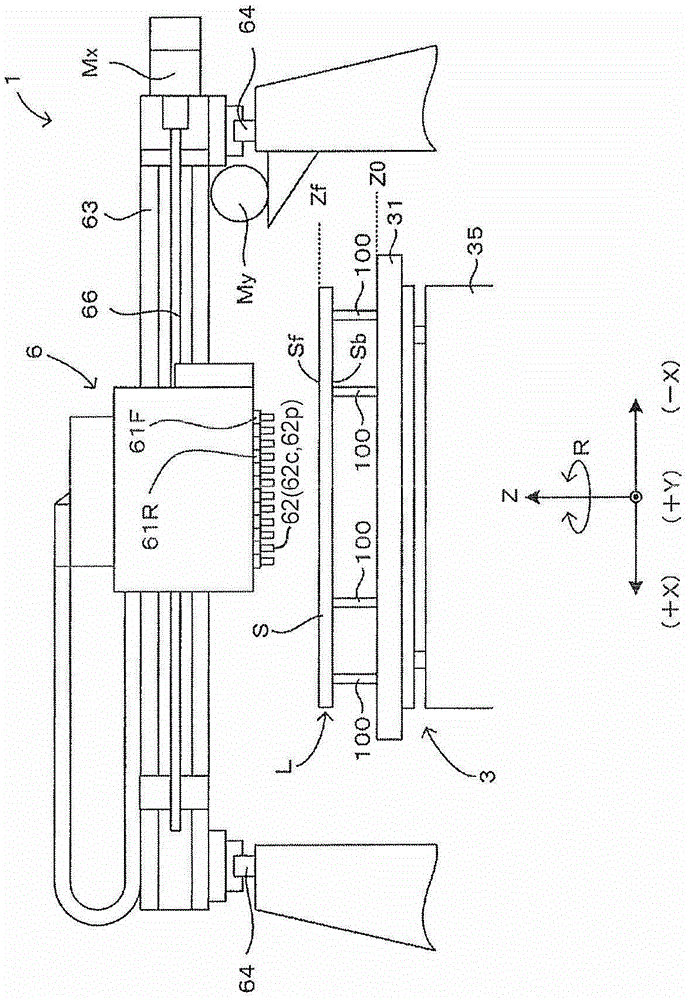
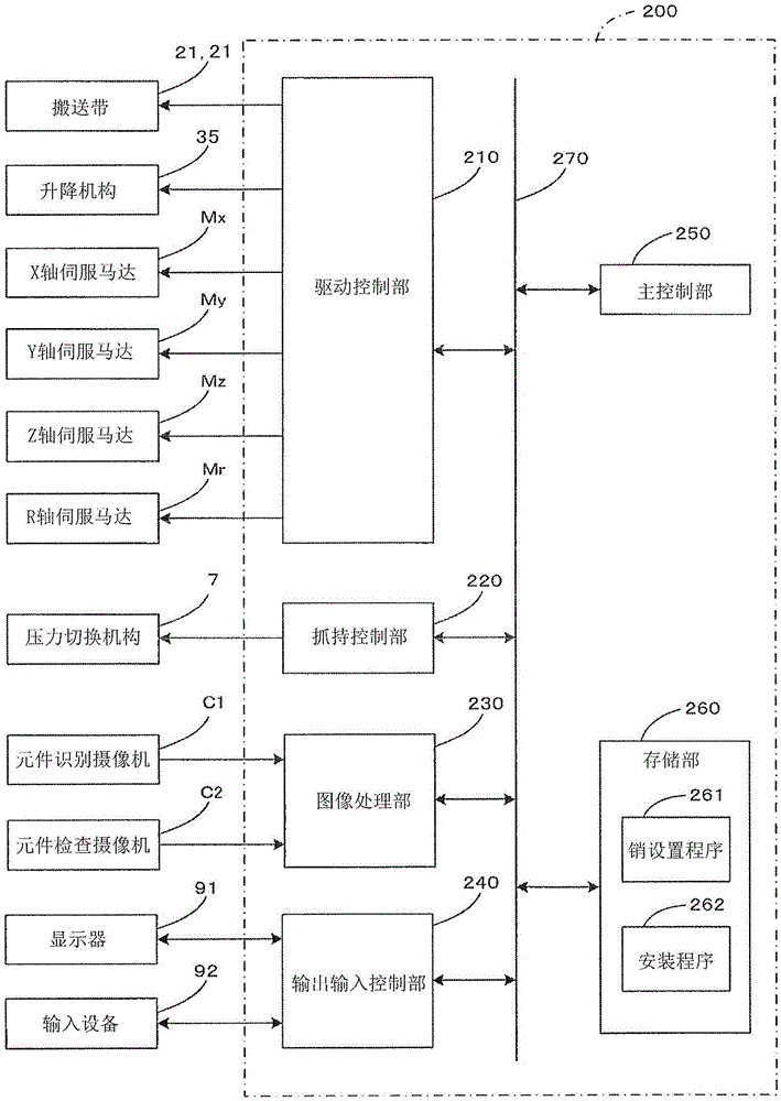
[0016] figure 1 It is a plan view showing the schematic structure of the component mounting apparatus 1 according to the embodiment of the present invention, figure 2 is a partial front view of the component mounting device 1, image 3 It is a block diagram showing the main electrical configuration of the component mounting device 1 . The component mounting apparatus 1 shown in these figures has a structure capable of mounting both surface mount components and lead components P1 on the substrate S. In addition, in figure 1 , figure 2 In the drawings shown below, in order to clarify the directional relationship in each drawing, XYZ orthogonal coordinate axes with the Z-axis direction as the vertical direction are appropriately shown.

[0017] The component mounting apparatus 1 includes a base 11 and a substrate conveyance mechanism 2 provided on the base 11 , and can convey a substrate S in a predetermined conveyance direction X. More specifically, the substrate transfer...


PUM


Abstract

The present invention relates to a bending device for bending a lead wire of a lead component inserted into an insertion hole penetrating from one main surface of a substrate to the other main surface, and a component mounting device, comprising: a lead wire receiving part, The other main surface side of the substrate is in contact with the lead of the lead component inserted into the insertion hole of the substrate from the one main surface of the above-mentioned substrate toward the component mounting direction of the other main surface, so that the above-mentioned lead is bent; A seat member supports the above-mentioned lead wire receiving member. The lead wire receiving member is supported on the base member so as to be displaced in a plane perpendicular to the component mounting direction by a force from the lead wire received by the lead wire receiving member in contact with the lead wire. Accordingly, even when the positional relationship between the insertion hole of the substrate and the bending device is not appropriate, the lead wire can be brought into proper contact with the bending device, the lead wire can be reliably bent, and the lead element can be reliably mounted on the substrate.

Description

technical field [0001] The present invention relates to a bending technique for mounting a lead component on a substrate by bending a lead of a lead component inserted into an insertion hole formed on a substrate. Background technique [0002] Japanese Laid-Open Publication No. Hei 06-112692 discloses a clinch mechanism that inserts the leads of lead components into mounting holes (insertion holes) formed on the substrate, and inserts the leads protruding from the substrate. The distal ends of the leads are bent, thereby mounting the lead elements on the substrate. This bending mechanism includes a head unit provided above the substrate and a bending unit provided below the substrate. When the head unit inserts the lead wire of the lead element into the mounting hole from above the substrate, the bending unit contacts the distal end of the lead protruding below the substrate. The bending unit is formed with a beveled inclined surface, and the distal end of the lead wire in...

Claims


Application Information

Patent Timeline
Patent Type & Authority Patents(China)
IPC IPC(8): H05K13/00H05K13/02
Inventor 西城洋志野末智之
Owner YAMAHA MOTOR CO LTD
Why Eureka
Try Eureka