
A pressureless coin flipping device

A coin flipping technology, applied in the direction of transportation and packaging, conveyor objects, etc., can solve the problems of easily damaged coin surfaces and belt wear, and achieve the effect of avoiding wear and tear

Active Publication Date: 2015-08-12
NANJING CBPM GREAT WALL FINANCIAL EQUIP
View PDF2 Cites 1 Cited by
  • Summary
  • Abstract
  • Description
  • Claims
  • Application Information

AI Technical Summary

Problems solved by technology

Although these two types of existing devices are reliable for turning over, they all need to hold the coin by means of a conveyor belt for turning over, so it is easy to damage the surface of the coin and wear the belt

Method used


Image

  • A pressureless coin flipping device
  • A pressureless coin flipping device
  • A pressureless coin flipping device

Examples


Embodiment Construction

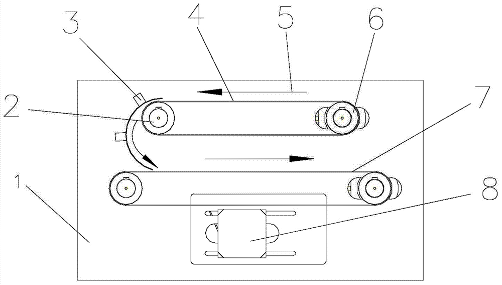
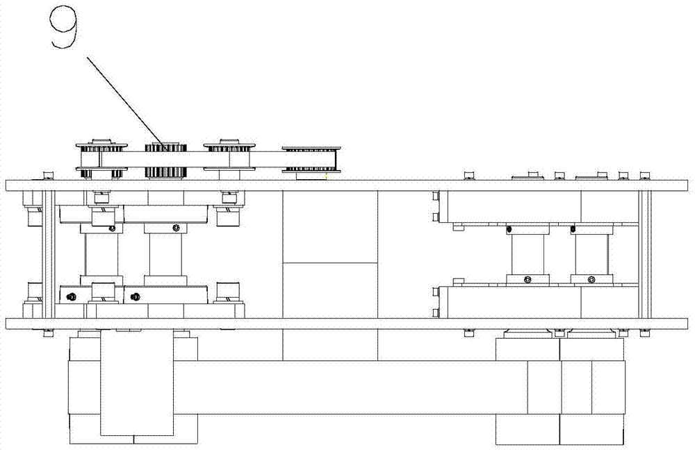
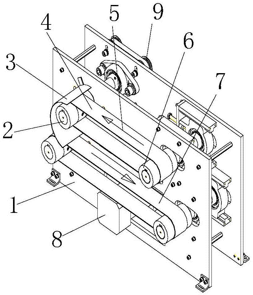
[0023] The coin turning device of the present embodiment is as Figure 1 to Figure 3 As shown, the upper and lower sides of the frame wallboard 1 are respectively provided with a first-stage conveyor belt 4 and a second-stage conveyor belt 7 parallel to each other, and the looping motion directions of the two-stage conveyor belts are opposite. The output end of the first-stage conveyor belt 4 is connected with the input end of the second-stage conveyor belt 7 by a C-shaped reverse coin guide plate 3, and the upper end of the C-shaped reverse coin guide plate 3 is connected to the first-stage conveyor belt 4. There is a distance greater than the thickness of the coin between the highest points, and the lower end of the C-shaped reversed coin guide plate 3 extends and connects toward the conveying direction of the second-stage conveyor belt. The distance should be as small as possible to minimize the jumping of the coin after it falls on the belt, so as to keep the stability of ...


PUM


Abstract

The invention relates to a non-pressure coin turn-over device, and belongs to the technical field of coin making equipment. The non-pressure coin turn-over device comprises a first-level conveying belt and a second-level conveying belt which are arranged in an up-down mode and have different motion directions. The output end of the first-level conveying belt is connected with the input end of the second-level conveying belt through a C-shaped turn-over coin guide plate. A gap is formed between the upper end of the C-shaped turn-over coin guide plate and the peak of the first-level conveying belt, and the width of the gap is larger than the thickness of a coin. The lower end of the C-shaped turn-over coin guide plate extends for connection along the conveying direction of the second-level conveying belt. By the non-pressure coin turn-over device, turn-over conveying of coins can be completed without any pressure, stability and reliability are guaranteed, and abrasion and damage to surfaces of the coins are completely avoided.

Description

technical field [0001] The invention relates to a coin turning device, in particular to a pressureless coin turning device, which belongs to the technical field of coinage equipment. Background technique [0002] According to the applicant's understanding, existing coin turning device mainly contains two types, and a class is C-type bagging and conveying turning device, is disclosed by the Chinese patent that application number is 200310106384.7; Surface device, disclosed by Chinese patent application number 201210063107.1. Although these two types of existing devices are reliable for turning over, they all need to clamp the coin by means of a conveyor belt to turn over, so it is easy to damage the surface of the coin and wear the belt. Contents of the invention [0003] The object of the present invention is to solve the above-mentioned shortcomings in the prior art, and propose a coin turning device that can not only achieve short-distance reliable turning, but also doe...

Claims


Application Information

Patent Timeline
Patent Type & Authority Patents(China)
IPC IPC(8): B65G47/24
Inventor 陈刚李晓春孙平平
Owner NANJING CBPM GREAT WALL FINANCIAL EQUIP
Learn More