Structurally-improved fence weaving machine

A fence weaving machine and improved structure technology, applied in mechanical equipment, sugarcane machining, etc., can solve problems affecting product aesthetics and yield, insufficient mechanization, affecting machine continuity, etc., to achieve simple procedures and avoid waste Effect of regularity, increased speed

Active Publication Date: 2015-03-18
ZHEJIANG MINZO NEW MATERIALS CO., LTD
View PDF3 Cites 0 Cited by
  • Summary
  • Abstract
  • Description
  • Claims
  • Application Information

AI Technical Summary

Problems solved by technology

Although the fence weaving machine can provide certain convenience for fence weaving, the patented product also has the following disadvantages: 1. The degree of mechanization is not high enough, and the feeding process still needs to be done manually, which is easily restricted by the operation proficiency of workers. And affect the continuity of the whole machine production; 2. The weaving of the fence in this patented product is carried out through continuous shuttle changing operations. Because the whole mechanism is very complicated, it is easy to cause the machine to jam due to insufficient shuttle changing during the operation process. At this time, workers are required to assist in changing shuttles, which affects the continuity of work; 3. This patented product can only weave hard fence materials such as wooden strips and bamboo strips, but not soft materials such as plastics. If the above-mentioned patented machine is used for weaving, the machine will easily cause the leaves to fall off, which will affect the aesthetics and yield of the entire product

Method used


Image

  • Structurally-improved fence weaving machine
  • Structurally-improved fence weaving machine
  • Structurally-improved fence weaving machine

Examples


Embodiment Construction

[0023] The following are specific embodiments of the present invention and in conjunction with the accompanying drawings, the technical solutions of the present invention are further described, but the present invention is not limited to these embodiments.

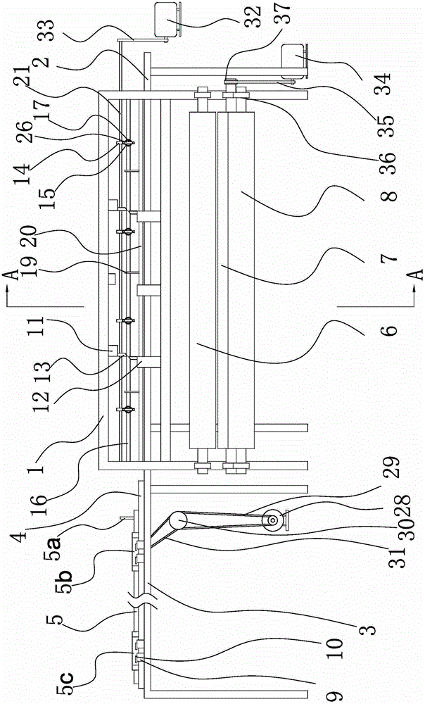
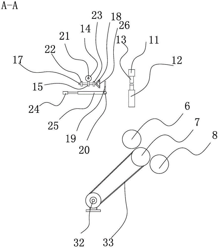
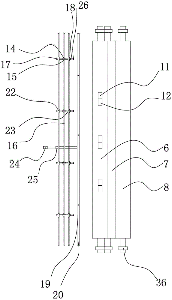
[0024] refer to figure 1 , figure 2 with image 3 , the present embodiment is a machine for weaving fences, including a frame 1, a feeding mechanism, a winding and weaving mechanism, a cutting mechanism and a discharging mechanism, as well as a motor that drives the above-mentioned mechanism, a cylinder 24 and an electric control device. Control devices include travel switches, relays, electric control valves, buttons, etc.

[0025]The feeding mechanism includes a slide bracket with a slide rail 4 and a pull rod 5 erected on the slide rail 4 . The sliding bracket is composed of a feeding rack 2 and a buffer rack 3. The feeding rack 2 is located at the frame 1, the buffer rack 3 is set on the side of the rack 1, and the...


PUM


Abstract

The invention provides a structurally-improved fence weaving machine and belongs to the technical field of machinery. The structurally-improved fence weaving machine solves the problem that an existing fence weaving machine cannot achieve effective mechanical automation production. The structurally-improved fence weaving machine comprises a machine frame, a winding and weaving mechanism, a discharge mechanism, a plurality of motors for driving the winding and weaving mechanism and the discharge mechanism, and an electric control device. The structurally-improved fence weaving machine is characterized by further comprising a feeding mechanism, and the feeding mechanism comprises a sliding support with a sliding rail, and a material pulling rod which is arranged on the sliding rail in an erection mode, one end of the material pulling rod is provided with a feeding puller which is used for pulling fence materials, the other end of the material feeding rod is connected with the motor I through a transmission mechanism I, and the motor I is connected with the electric control device. Due to the fact that the structurally-improved fence weaving machine is additionally provided with the feeding mechanism, the feeding is more accurate, raw materials cannot be damaged, enterprise costs are saved and the enterprise efficiency is improved. The structurally-improved fence weaving machine is simple in structure, convenient to operate, time-saving and labor-saving.

Description

technical field [0001] The invention belongs to the technical field of machinery, and relates to a weaving device, in particular to a fence weaving machine with an improved structure for automatically weaving fence strips. Background technique [0002] At present, artificial plant fences are generally made by hand weaving. By weaving a series of fence strips into sheets, the labor intensity is high and the production efficiency is low, which makes the cost high. Chinese patent (Patent No.: 200710051472.X) discloses a fence weaving machine. There are upper and lower rollers at the front of the machine, and a flywheel at one end of the shaft of the upper roller. The flywheel is connected with a chain. return spring connection; the middle and upper part of the frame has a cross bar connected with the cylinder, and a row of hook changing columns connected to the upper shuttle is arranged at the bottom of the cross bar; the middle and lower part of the frame has a shuttle changin...

Claims


Application Information

Patent Timeline
Patent Type & Authority Patents(China)
IPC IPC(8): B27J1/02
Inventor 徐世虎
Owner ZHEJIANG MINZO NEW MATERIALS CO., LTD
Why Eureka
Try Eureka