Eureka AIR delivers breakthrough ideas for toughest innovation challenges, trusted by R&D personnel around the world.

Disassembly and assembly device of valve assembly

A technology for installing devices and valves, which is applied to hand-held tools, manufacturing tools, etc., can solve the problems of high labor intensity of operators, low assembling success rate, and difficulty in locking blocks, and achieves low labor intensity, light use and low cost. Effect

Active Publication Date: 2015-07-22
ZHEJIANG OCEAN UNIV
View PDF10 Cites 0 Cited by
  • Summary
  • Abstract
  • Description
  • Claims
  • Application Information

AI Technical Summary

Problems solved by technology

[0005] At present, the process of disassembling and installing the valve in China is basically directly pressing the spring manually. This method requires the cooperation of two people to complete, and accidents may occur due to the collapse of the lock clip when the valve lock clip is removed; or use simple tools, use The palm of the hand presses the tooling to overcome the force of the valve spring. In the case of a high spring stiffness, a very large force is required. People with poor strength generally cannot press it. Because the gap between the valve and the spring seat is small, the lock block falls. It is difficult to enter the lock groove of the air door; or use the principle of leverage to directly press the spring down, and effective adjustment is required, and the success rate of assembly is very low. This kind of operation has certain hidden dangers, and the labor intensity of the operator is relatively high.

Method used


Image

  • Disassembly and assembly device of valve assembly
  • Disassembly and assembly device of valve assembly
  • Disassembly and assembly device of valve assembly

Examples


Embodiment Construction

[0021] In order to make the object, technical solution and advantages of the present invention clearer, the present invention will be further described in detail below in conjunction with the accompanying drawings and examples. However, the examples given are not intended to limit the present invention.

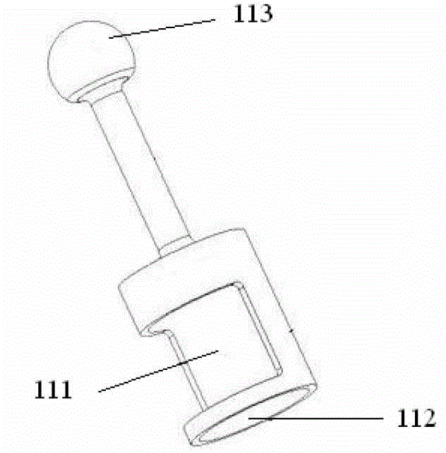
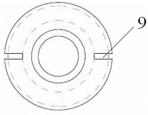
[0022] see Figure 5 , the embodiment of the present invention includes a bracket 1, a pull rod 2, a safety ring 3 and an adjustment nut 4, the pull rod is a cylindrical structure, and the figure 2 , the lower part of which is a hollow inner cavity, the bottom edge of the pull rod is provided with an outer edge 6, the safety ring is sleeved on the bottom end of the pull rod, and is stuck on the outer edge, and the bottom of the inner cavity is provided with a boss 7 and a notch 12 of the valve Matching, the lower part of the pull rod has a flaring groove 9 along the axial direction; the bracket is a cylindrical sleeve, the upper end of the bracket is provided with a through...


PUM


Abstract

The invention provides a disassembly and assembly device of a valve assembly, and relates to the technical field of maintenance tools of engine parts. The disassembly and assembly device comprises a bracket, a pull rod, a safety ring and an adjusting nut, wherein the pull rod has a cylinder structure; the lower part of the pull rod is provided with a hollow cavity, and the bottom edge of the pull rod is provided with an outer edge; the safety ring is sleeved on the bottom end of the pull rod and is clamped on the outer edge; the bottom of the cavity is provided with a boss to be matched with a notch of a valve; the lower part of the pull rod is provided with a flare groove along the axis; the bracket is a cylindrical sleeve; the upper end of the bracket is provided with a through hole; the pull rod penetrates through the through hole to be arranged in the bracket; the upper part of the pull rod is provided with external thread which is matched with the adjusting nut; and the lower part of the bracket is provided with an open groove. The disassembly and assembly device is used without being limited to the place, and has the advantages of lightness and convenience in use, easiness in operation, low cost, safety, reliability, capability of reducing the labor intensity of operation workers and suitability for maintenance.

Description

technical field [0001] The invention relates to the technical field of maintenance tools for engine parts, in particular to a device for dismounting and installing a valve assembly of a diesel engine. Background technique [0002] During the repair process of domestic diesel engines, the intake and exhaust valves of the diesel engine are often disassembled, such as the repair of the valve line, the replacement of the valve guide, etc. Composed of two halves), take out the upper spring plate, inner and outer springs, lower spring plate, and finally take out the valve from the guide tube. At present, the valve lock clips on the production line are generally assembled using a special valve lock clamp machine, but during the maintenance process, the maintenance personnel often hold two round rods (such as valve tappets) with both hands to press the upper seats of the valve springs on both sides of the valve. The edge is removed and the lock clip is installed. [0003] Or, ofte...

Claims


Application Information

Patent Timeline
Patent Type & Authority Patents(China)
IPC IPC(8): B25B27/14
Inventor 王伟军李玉乐王帅军陈甜龚雅萍
Owner ZHEJIANG OCEAN UNIV
Why Eureka
Eureka Blog
Learn More