Pipe machine

A technology of pipe arranging machine and conduit, which is applied to detonators, attack equipment, etc., can solve the problems of difficult automatic sorting of pipe shells and complicated automatic sorting devices, etc., and achieve the effect of improving pipe arranging efficiency and saving costs.

Active Publication Date: 2015-12-23
SHANDONG YINGUANG TECH CO LTD
View PDF6 Cites 0 Cited by
  • Summary
  • Abstract
  • Description
  • Claims
  • Application Information

AI Technical Summary

Problems solved by technology

[0006] The purpose of the present invention is to solve the problems in the prior art that the pipe shells are difficult to be automatically sorted, or the automatic sorting device is very complicated, and provide a pipe arrangement with a simple structure, easy sorting, and automatic sorting. machine

Method used


Image

  • Pipe machine
  • Pipe machine
  • Pipe machine

Examples


Embodiment Construction

[0023] Below in conjunction with accompanying drawing, the concrete embodiment of pipe arrangement machine of the present invention is described in detail.

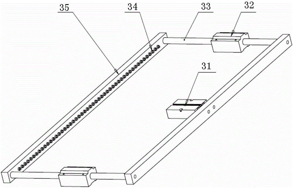
[0024] First refer to figure 1 , figure 1 It is an assembly schematic diagram of the pipe arrangement machine of the present invention. It includes a storage smoothing mechanism 1, a locking head 2, a turning mechanism 3, a feeding conduit 4, a conduit mold 5, a push-in cylinder 6, a push-out cylinder 7 and a frame 8.

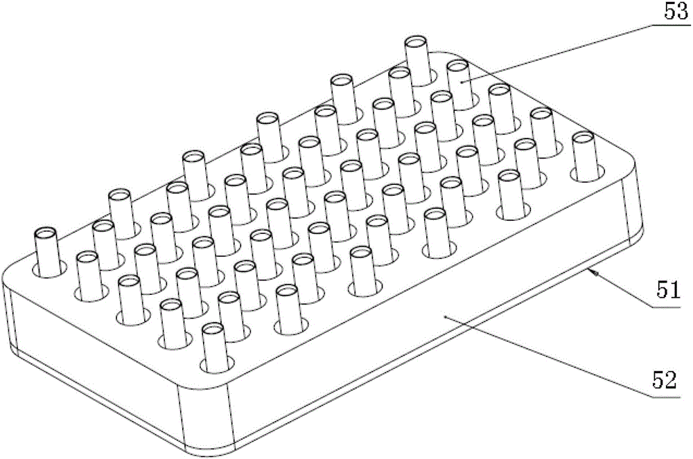
[0025] The above-mentioned mechanisms are all arranged on the frame 8, wherein the storage and arrangement mechanism 1 is fixed on the uppermost part of the frame, and the detonator shell 53 that has been straightened out by the storage and arrangement mechanism 1 enters and is arranged on the frame through a row of inclined slideways. In a row of locking heads 2, the function of the locking head 2 is to lock the casing 53, and send it to the feeding conduit 4 through the U-turn mechanism 3, wherein the ...


PUM


Abstract

The invention discloses a tube drawing bench comprising an arranging unit used for clearing up stored tubes, a locking head, a turning unit, blanking pipes, pipe moulds, a pulling cylinder, a pushing cylinder and a frame. The arranging unit comprises an accumulation hopper, a disturbance device, a clearing up groove and a slide rail; the turning unit comprises a turning cylinder, a sliding bearing, a turning rod, turning nail blocks and turning nails. The tube drawing bench is used by following steps: the tubes for arrangement is cleared up in the arranging unit, delivered to the turning unit through the slide rail and the locking head; the tubes with lower ends down are delivered directly into the blanking pipes, and the tubes with upper ends down are turned around by the turning unit and then also delivered into the blanking pipes; the tubes are delivered into the pipe moulds through the blanking pipes; the pipe moulds provided with the tubes are pushed out of the tube drawing bench by the pushing cylinder, and the pipe moulds which are not provided with the tubes are pulled into the tube drawing bench by the pulling cylinder for further arrangement. The tubes can be subtly turned around by the turning unit, so that automatic separation is realized, tube drawing efficiency is increased, and cost is saved greatly.

Description

technical field [0001] The invention relates to a production equipment for civil explosive materials, in particular to an automatic pipe-arranging machine equipment for arranging detonator shells. Background technique [0002] In the production process of detonators, the automatic discharge of empty detonator shells, especially metal shells with one end closed, has always been a problem that plagues the production of detonators. At present, the production of metal shell detonators mainly uses manual discharge of tubes, which has a low working efficiency and affects the production of detonators. Reduced the production output of detonator, increased production cost. [0003] The main technical problems restricting the automatic discharge of detonator shells are: firstly, it is necessary to automatically introduce the messy and disorderly metal shells into a certain track; The requirements of the two are strictly separated, that is, the directional arrangement, and the third i...

Claims


Application Information

Patent Timeline
Patent Type & Authority Patents(China)
IPC IPC(8): C06C7/02
Inventor 陈月畅张海伟王恩东刘文成李伟杨英杰
Owner SHANDONG YINGUANG TECH CO LTD
Why Eureka
Try Eureka