
Milk foaming machine

A foaming machine and milk technology, which is applied in the field of equipment for preparing milk foam, can solve problems such as insufficient milk foaming and fineness, air can no longer be mixed in, milk foaming is not sufficient, etc., and the operation process is simple and easy Easy to use, simple product structure, and low cost

Active Publication Date: 2013-09-11
熊兴剑
View PDF10 Cites 17 Cited by
  • Summary
  • Abstract
  • Description
  • Claims
  • Application Information

AI Technical Summary

Problems solved by technology

However, the general problem of existing mechanical stirring and foaming appliances is that the amount of unfoamed milk left in the container is too much, and the milk foaming is not sufficient; the reason is that when the agitator rotates to stir the milk, About half of the working time of the mixer, the mixer used for foaming is almost covered by a part of the milk foam that has been foamed, so that the air can no longer be mixed into the foaming area near the mixer at the lower part of the container. At this time, although the agitator is still rotating, since almost no new air is introduced into the vicinity of the agitator, the remaining milk at the bottom of the container is affected to continue to foam, resulting in a large amount of remaining unfoamed milk , making the milk froth insufficient and delicate, and also affecting the persistence of the milk froth

Method used


Image

  • Milk foaming machine
  • Milk foaming machine
  • Milk foaming machine

Examples


Embodiment 1

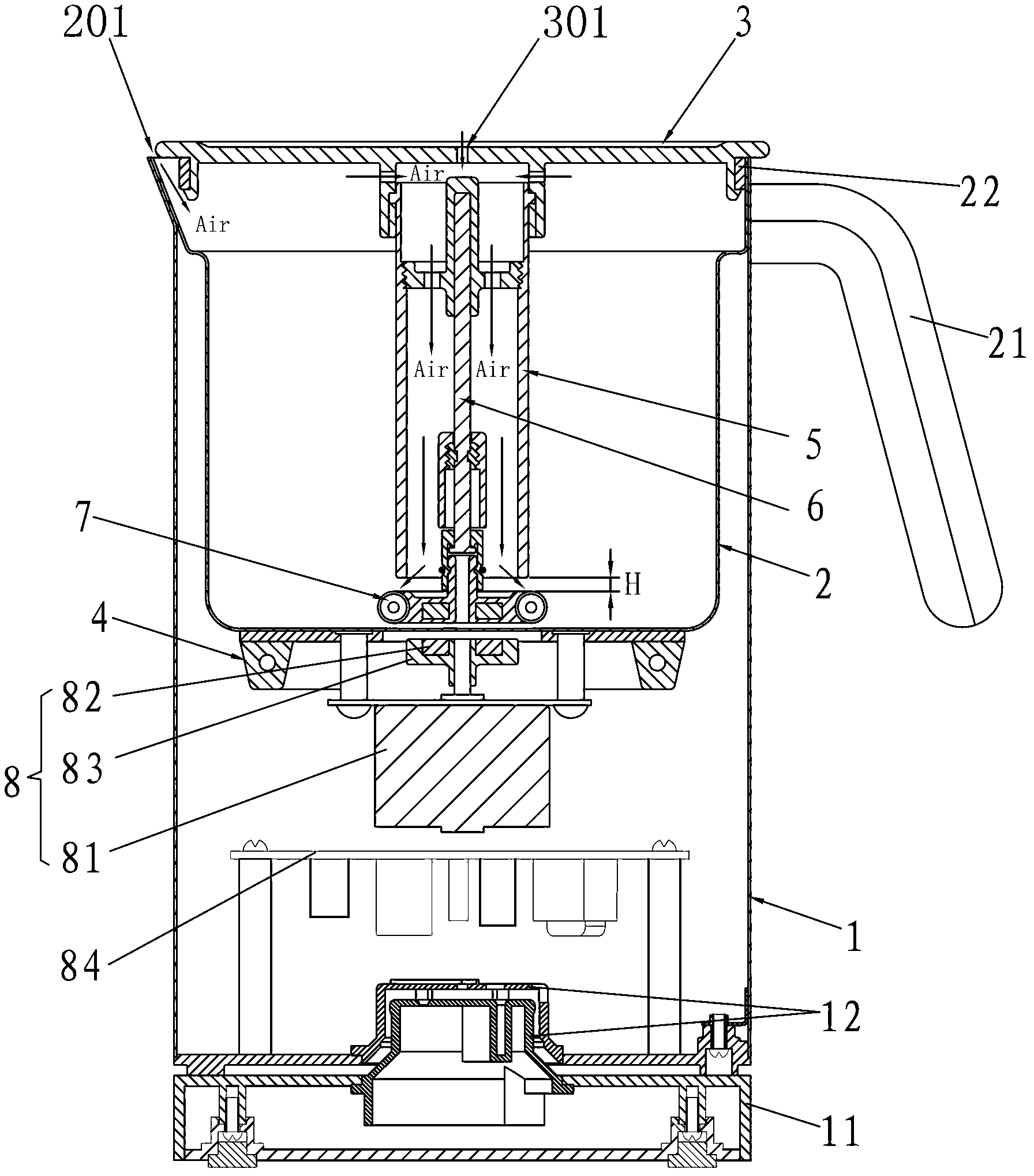
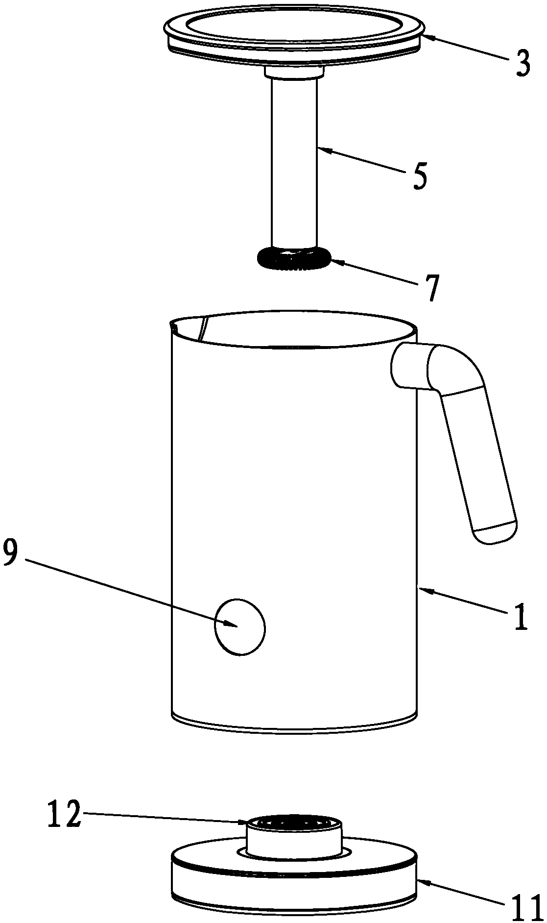
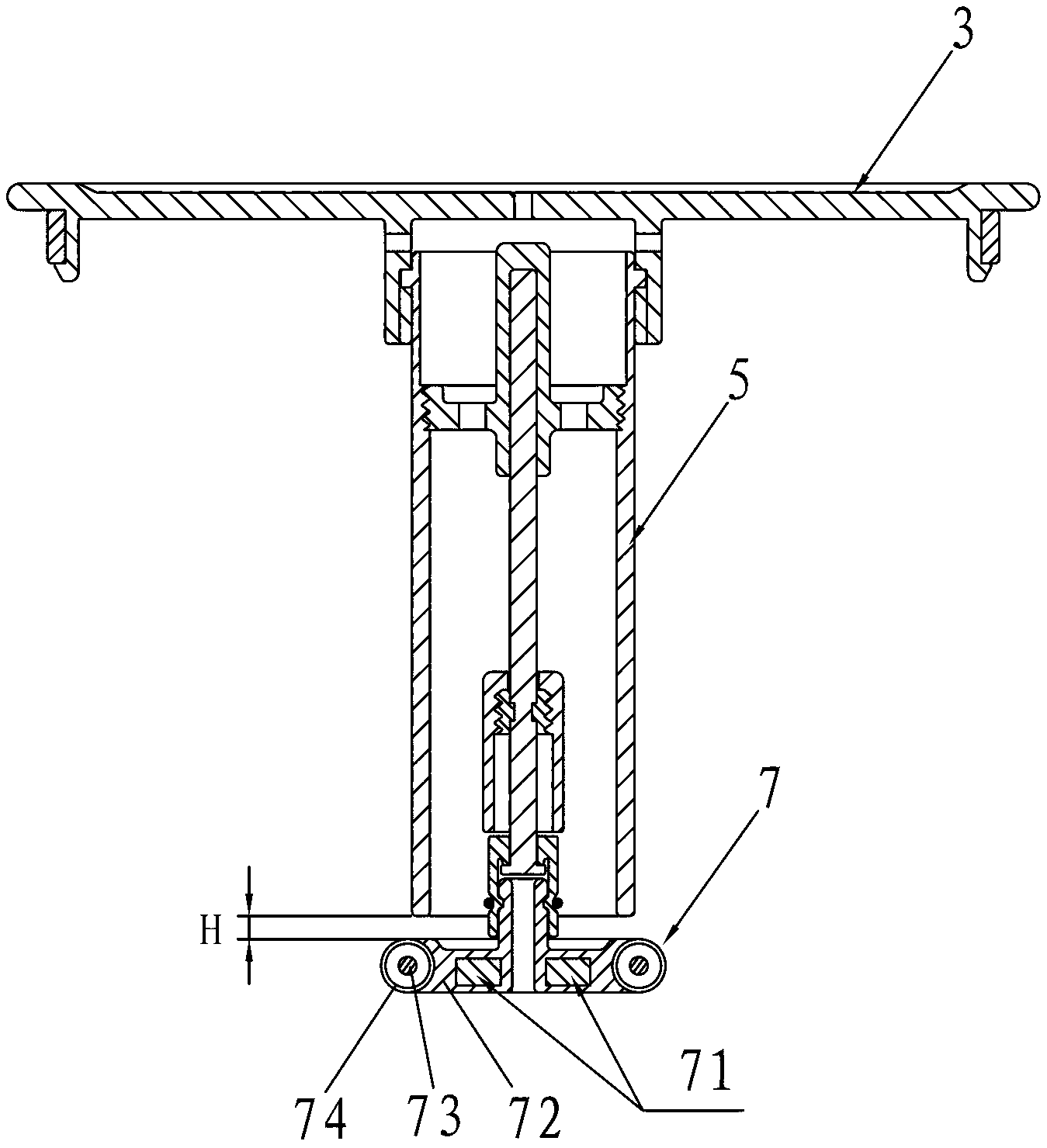
[0038] Such as figure 1As shown in Figure 6(b), the present invention provides a milk foaming machine, which includes a casing 1, a container cover 3 and a silicone anti-vibration ring 22 arranged on the side wall of the container cover 3, and a container 2 is arranged in the casing 1 And the heating device 4 and the magnetic driving device 8 for heating the container 2, the magnetic driving device 8 includes a motor 81, a driving magnet disk 83 and a magnet 82, and a magnet 82 is arranged in the driving magnet disk; The driving device is arranged below the container 2; the agitator 7 arranged in the container 2 has a built-in magnet 71; composition. The lower end of the housing 1 is provided with a power-taking connector 12 and a detachable power-taking base 11, a handle 21 is provided on the upper part of the housing, and a switch 9 is also provided on the housing; the upper end of the container 2 is set as an opening, and the container cover 3 is set at the upper end of t...

Embodiment 2

[0047] Such as Figure 7 and Figure 8 As shown, the principle of the second embodiment is the same as that of the first embodiment above, and the structure is similar, the difference is that the connection mode between the stirring shaft 6 and the air pipe 5 is different.

[0048] Such as figure 1 As shown in Figure 6(b), the present invention provides a milk foaming machine, which includes a casing 1, a container cover 3 and a silicone anti-vibration ring 22 arranged on the side wall of the container cover 3, and a container 2 is arranged in the casing 1 And the heating device 4 and the magnetic driving device 8 for heating the container 2, the magnetic driving device 8 includes a motor 81, a driving magnet disk 83 and a magnet 82, and a magnet 82 is arranged in the driving magnet disk; The driving device is arranged below the container 2; the agitator 7 arranged in the container 2 has a built-in magnet 71; composition. The lower end of the housing 1 is provided with a p...

Embodiment 3

[0066] The principle of this embodiment is the same as that of Embodiment 2, and the difference from the milk foaming machine in Embodiment 2 lies in the structure for realizing the quick release function of the agitator.

[0067] As another way to realize the quick release function, in this embodiment, such as Figure 14 As shown, the stirring shaft 6 is rotatably provided with a rotating connecting ring 66 , the rotating connecting ring 66 has a built-in magnet 63 , and the stirrer 7 has a built-in magnet 71 , and the rotating connecting ring 66 is magnetically connected to the stirrer 7 . The stirrer 7 is magnetically attracted to the magnet 63, and the user can easily remove the stirrer 7 for cleaning.

[0068] Specifically, the magnetic pole N on the upper magnet surface of the built-in magnet 71 of the agitator 7 forms a detachable magnetic connection with the magnetic pole S on the lower magnet surface of the built-in magnet 63 of the rotating connection ring 66, and th...


PUM


Abstract

The invention belongs to the field of devices for forming foam through milk, and provides a milk foaming machine. The milk foaming machine comprises an outer shell, a container cover and a magnetic driving device. A container and a heating device are arranged in the outer shell. The magnetic driving device is arranged under the container. The container cover is arranged at the upper end of the container. An air pipe is arranged in the container and communicated with the outside of the container. The lower end of the air pipe is connected to a stirring shaft. A stirrer is connected to a portion, at an outlet of the lower end of the air pipe, of the stirring shaft. The lower end of the air pipe is provided with an opening. According to the milk foaming machine, in the overall rotating operation process of the stirrer, air is continuously led into a foaming area nearby the stirrer via the air pipe located above the stirrer through negative pressure generated by the stirrer during rotation, so that the air needed for continuous stirring and foaming is supplied, and the milk foaming is more sufficient and fine. Moreover, the milk foaming machine is simple in structure, fast to produce and assemble, low in cost, convenient to use by consumers, easy to clean and economical to use.

Description

technical field [0001] The invention relates to a device for preparing foam from milk, in particular to a milk foaming machine. Background technique [0002] At present, the utensils for preparing foam with milk on the market mainly contain steam foaming utensils and mechanical stirring and foaming utensils. [0003] Appliances that use steam foaming generally use a steam generating device to deliver steam to a container containing milk through a steam pipe. This method of using steam to generate milk foam requires additional steam generating devices and steam delivery devices. The structure is relatively complicated, and the cost is high. At the same time, the foaming effect has a lot to do with the user's operating skills. Poor user's operating skills will lead to unsatisfactory foaming effect. [0004] A mechanical stirring and foaming device is used to form milk foam by rotating the stirrer in a container containing milk at an appropriate speed, quickly incorporating an...

Claims


Application Information

Patent Timeline
Patent Type & Authority Applications(China)
IPC IPC(8): A47J31/00A47J31/44A47J43/07
Inventor 熊兴剑
Owner 熊兴剑
Learn More