
Three-dimensional (3D) camera lens and 3D camera system

A 3D and lens technology, applied in the field of 3D lens and camera system for shooting based on the above-mentioned lens, can solve problems such as difficulty in meeting shooting requirements, deterioration of image quality, misalignment of front group lens and rear group lens, etc., and achieve convenient shooting , the effect of simplifying the structure

Inactive Publication Date: 2013-08-07
张伟 +1
View PDF10 Cites 4 Cited by
  • Summary
  • Abstract
  • Description
  • Claims
  • Application Information

AI Technical Summary

Problems solved by technology

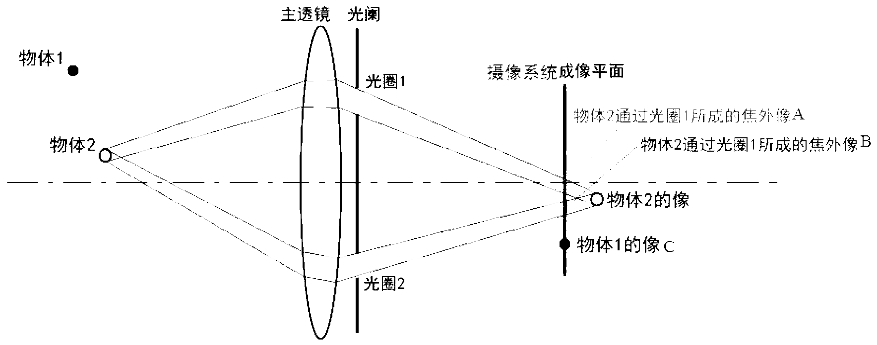
However, there are still many problems in the existing single-lens solutions. For example, the 3D single-lens designed by Sony uses the offset of the rear group lens to achieve parallax, which leads to the misalignment of the front group lens and the rear group lens, which leads to poor image quality. Deterioration, and the parallax formed is very small, it is difficult to meet higher shooting requirements

Method used


Image

  • Three-dimensional (3D) camera lens and 3D camera system
  • Three-dimensional (3D) camera lens and 3D camera system
  • Three-dimensional (3D) camera lens and 3D camera system

Examples


Embodiment 1

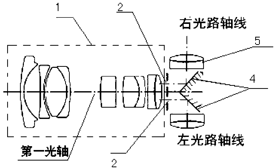
[0074] Embodiment one (see image 3 ), the two first reflectors 4 are respectively located at the rear side of a pair of apertures (the meaning of the rear side referred to in the text is that the side of the exit light path of the corresponding component corresponds to the right side of the figure at the same time), and each first reflector The mirror is at an angle of 45 degrees to the axis of one aperture, so that the light passing through one aperture can propagate outward along the direction perpendicular to the first optical axis. and, due to image 3 Among them, the sides of a pair of second reflectors close to each other are parallel, that is, symmetrically distributed in the paper, and the left optical path axis and the right optical path axis are actually on the same straight line.

Embodiment 4

[0075] Embodiment four (see Figure 5 ), a pair of apertures are distributed perpendicular to the paper surface, and like Embodiment 1, are distributed symmetrically with respect to the first optical axis, and the axes of the apertures are parallel to the first optical axis. At this time, each aperture corresponds to a first reflecting mirror. At this time, the sides where the two first reflecting mirrors 4 are close to each other are staggered, that is, they are distributed perpendicularly to the paper, and the reflected left optical path axis and right optical path The axes are parallel to each other in a plane perpendicular to the first optical axis.

Embodiment 5

[0076] Embodiment five (see Figure 6 ) is also similar to Embodiment 1, a pair of apertures are distributed perpendicular to the paper surface, in this embodiment, only a first reflector 4 is arranged on the rear side of one of the apertures, and the first reflector and one of the apertures The axis of the aperture is 45 degrees, and the rear side of the other aperture does not place the first reflector, and the light passes directly through it for imaging.


PUM


Abstract

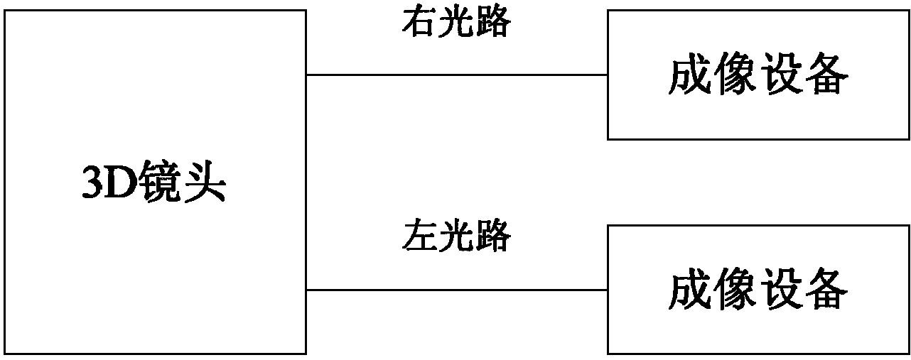
The invention discloses a three-dimensional (3D) camera lens and a 3D camera system. The 3D camera lens comprises a first lens assembly and a pair of apertures, wherein the first lens assembly is provided with a first optical axis; the pair of apertures is arranged on the rear side of the first lens assembly, the axis of at least one aperture does not intersect with the first optical axis, so that the transmission light of the first lens assembly respectively passes through the apertures to respectively form a left-eye image and a right-eye image, and a parallax error exists between the left-eye image and the right-eye image. The 3D camera lens comprises a third lens assembly, wherein the third lens assembly comprises an integral structure formed by two lens assembly parts, each lens assembly part is provided with a third optical axis, every two third optical axes are parallel to each other, the two lens assembly parts are respectively used for receiving two paths of light of a photographed object, the two paths of transmission light respectively form a left-eye image and a right-eye image, and a parallax error exists between the left-eye image and the right-eye image. The shooting of the 3D image and video is realized through one camera lens, so that the structure of equipment is greatly simplified.

Description

technical field [0001] The present invention relates to a lens and a camera system, in particular to a 3D lens capable of shooting 3D images and videos, and a camera system for shooting based on the lens. Background technique [0002] The principle of stereo vision is: human beings have two eyes. When human beings look at the same object, the images seen by the two eyes are slightly different due to the slightly different angles. Azimuth stereo vision. [0003] In order to simulate the stereoscopic vision of human beings, stereoscopic shooting has been produced. Specifically, two cameras are used to simulate human eyes, so as to realize the shooting of stereoscopic images. At present, there are dual-lens integrated DV players on the market, such as Sony PMW-TD300, but the picture quality and flexibility of this all-in-one machine are very limited, and it is only limited to the civilian field, while the professional field is still a dual-camera combination. . [0004] In t...

Claims


Application Information

Patent Timeline
Patent Type & Authority Applications(China)
IPC IPC(8): G03B35/10G02B13/00H04N5/225
Inventor 张伟
Owner 张伟
Learn More