A Single-Ended Traveling Wave Fault Location Method Using Timing Intervals of Positive and Negative Polarity Wave Heads
A technology of fault distance measurement and positive and negative polarity, which is applied in the direction of fault location, information technology support system, etc., and can solve problems such as large investment and large distance measurement error
- Summary
- Abstract
- Description
- Claims
- Application Information
AI Technical Summary
Problems solved by technology
Method used
Image
Examples
Embodiment 1
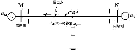
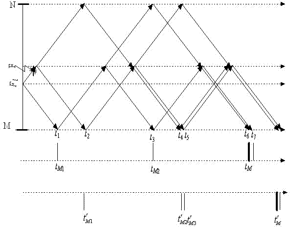
[0093] Example 1: Lightning strikes phase A of the transmission line, and the distance between the lightning strike point and the M terminal is 65 , the flashover point (fault point) is 80 meters away from the M terminal , the fault traveling wave waveform detected and recorded by the measuring terminal M is as follows Figure 5 As shown, the traveling wave data 4ms after the fault is intercepted, and the cubic B-spline wavelet function is used to perform wavelet transform on it to find the modulus maximum value. The result is as follows Image 6 shown. Starting from the moment when the initial traveling wave of the current first arrives at the M terminal, in the subsequent The polarity and arrival time of traveling wave heads with different properties are calibrated within the time length, and the results are shown in Table 1.
[0094] Table 1 Calibration results of positive and negative sequence traveling wave head timing when the lightning point is close to the M term...
Embodiment 2
[0107] Example 2: Lightning strikes phase A of the transmission line, and the distance between the lightning strike point and the M terminal is 95 , the flashover point (fault point) is 80 meters away from the M terminal , the fault traveling wave waveform detected and recorded by the measuring terminal M is as follows Figure 7 As shown, the traveling wave data 4ms after the fault is intercepted, and the cubic B-spline wavelet function is used to perform wavelet transform on it to find the modulus maximum value. The result is as follows Figure 8 shown. Starting from the moment when the initial traveling wave of the current first arrives at the M terminal, in the subsequent The polarity and arrival time of traveling wave heads with different properties are calibrated within the time length, and the results are shown in Table 2.
[0108] Table 2 Calibration results of positive and negative sequence traveling wave head timing when the flashover point is close to the M ter...
PUM
 Abstract
Description
Claims
Application Information
 - R&D
- Intellectual Property
- Life Sciences
- Materials
- Tech Scout
- Unparalleled Data Quality
- Higher Quality Content
- 60% Fewer Hallucinations
Browse by: Latest US Patents, China's latest patents, Technical Efficacy Thesaurus, Application Domain, Technology Topic, Popular Technical Reports.
© 2025 PatSnap. All rights reserved.Legal|Privacy policy|Modern Slavery Act Transparency Statement|Sitemap|About US| Contact US: help@patsnap.com


