
Light source device, light source generation method and laser projector with light source device

A light source device and light source technology, which is applied in the field of laser projection, can solve the problems of periodic light and dark changes of projection images and uneven brightness of images, reducing the quality of projection images, hidden dangers of motor safety, etc., so as to avoid periodic brightness changes and have a simple structure. , the effect of improving quality

Active Publication Date: 2015-04-22
HISENSE
View PDF4 Cites 0 Cited by
  • Summary
  • Abstract
  • Description
  • Claims
  • Application Information

AI Technical Summary

Problems solved by technology

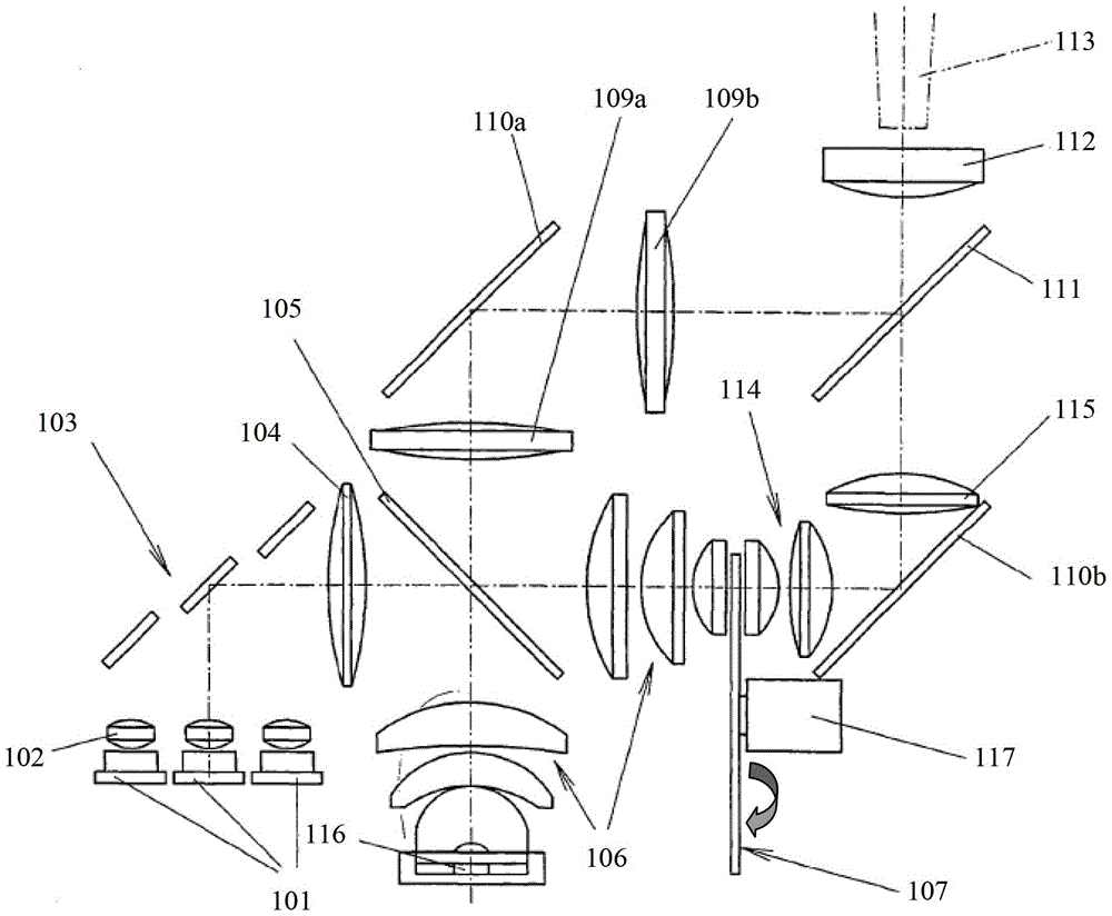
Therefore, when the rotating motor starts to rotate and the motor shaft of the rotating motor swings, the fluorescent wheel 107 will move back and forth relative to the predetermined design position, so that the light source generated by the above-mentioned light source device will also be The fluorescent wheel 107 moves back and forth to produce periodic brightness changes, thus causing periodic light and dark changes of the same projected picture and uneven brightness of the picture, reducing the quality of the projected picture
At the same time, the system of the above-mentioned existing light source device is also relatively complicated, and it is difficult to install and adjust.
In addition, in the light source device in the prior art, the high-speed rotating motor itself is also a potential safety hazard
[0013] It can be seen from the above that the light source device in the prior art still has some of the above-mentioned problems. Therefore, it is necessary to provide a better light source device, so as to avoid the problem of periodic brightness changes of the light source and improve the quality of the projected picture.

Method used


Image

  • Light source device, light source generation method and laser projector with light source device
  • Light source device, light source generation method and laser projector with light source device
  • Light source device, light source generation method and laser projector with light source device

Examples


Embodiment Construction

[0062] In order to make the object, technical solution and advantages of the present invention clearer, the present invention will be further described in detail below with reference to the accompanying drawings and examples.

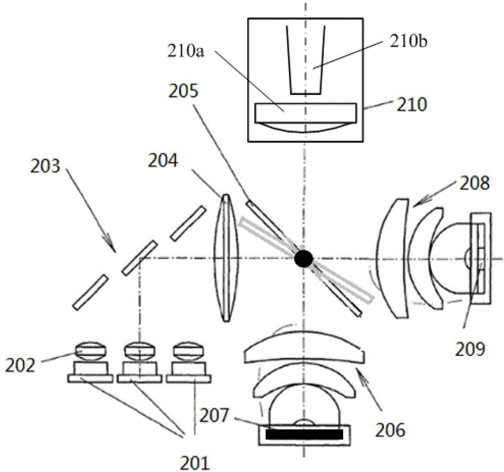
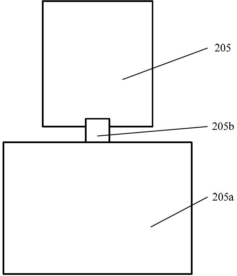
[0063] figure 2 It is a schematic diagram of the structure and principle of the light source device in the embodiment of the present invention. Such as figure 2 As shown, in a specific embodiment of the present invention, the light source device at least includes: a first laser light source 201, a collimating component 202, a reflecting component 203, a first light concentrating component 204, a dichroic component 205, and a driving component 205a ( figure 2 not shown), the second condensing component 206 , the wavelength converting component 207 , the fourth light source 209 , the third condensing component 208 and the light receiving component 210 . The fourth light source 209 may be an LED light source or a semiconductor laser light source.

...


PUM


Abstract

The invention discloses a light source device, a light source generation method and a laser projector with the light source device. The light source device comprises first laser light sources, collimation parts, a reflection part, a first condensation part, a dichroic part, a drive part, a second condensation part, a wavelength conversion part, a fourth light source, a third condensation part and a light receiving part. According to the light source device, the light source generation method and the laser projector with the light source device, the problem of periodical brightness variation generated by a light source can be effectively solved, and the quality of a projected image can be greatly improved.

Description

technical field [0001] The invention relates to laser projection technology, in particular to a light source device, a method for producing a light source and a laser projector including the light source device. Background technique [0002] In recent years, laser projectors have been widely used in various occasions due to their long life, high screen brightness and rich colors, such as TV projection, miniature projection, and some commercial, educational and home entertainment systems. [0003] As we all know, an optical picture needs to be composed of at least light waves of different dominant wavelengths, for example blue, green and red light waves. In the current existing technology, usually a light source of one wavelength is used as excitation light to generate a light source of another wavelength, and then time-shared emission with light sources of other wavelengths to display various pictures on the projection screen . For example, the blue laser emitted by the bl...

Claims


Application Information

Patent Timeline
Patent Type & Authority Patents(China)
IPC IPC(8): G03B21/20G02B27/10F21V13/00
CPCG02B26/08G02B27/106G03B21/2033G03B21/2053
Inventor 李巍
Owner HISENSE
Learn More