
Limit hook device

A hook device and position-limiting technology, which is applied in the field of hooks, can solve the problems of high production cost, difficult production process, unrestricted rotation angle, etc., and achieve the effect of low production cost, simple structure and convenient assembly

Active Publication Date: 2015-09-16
BEIJING AEONMED
View PDF6 Cites 0 Cited by
  • Summary
  • Abstract
  • Description
  • Claims
  • Application Information

AI Technical Summary

Problems solved by technology

[0004] The purpose of the present invention is to solve the problems of the existing hook device that the rotation angle cannot be limited, the production cost is high and the production process is difficult, and a limit hook device is provided, which has a simple structure, can effectively limit the rotation angle, and has low production cost. Advantages of low cost, simple process and convenient installation and use

Method used


Image

  • Limit hook device
  • Limit hook device
  • Limit hook device

Examples


Embodiment Construction

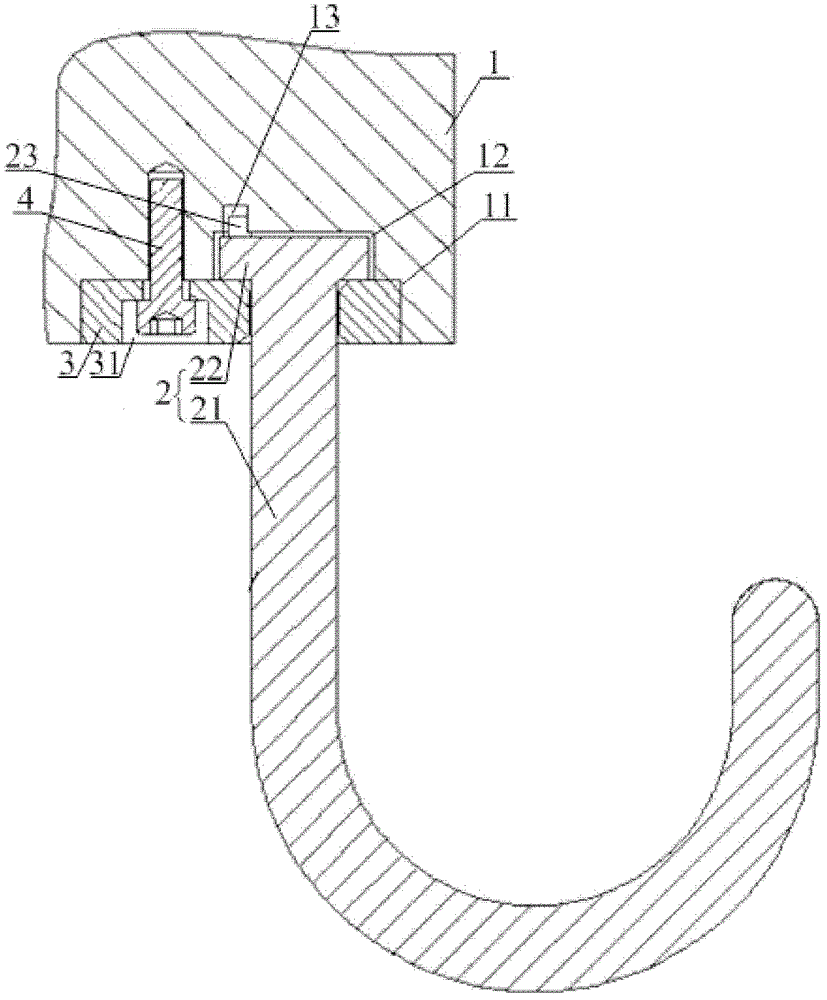
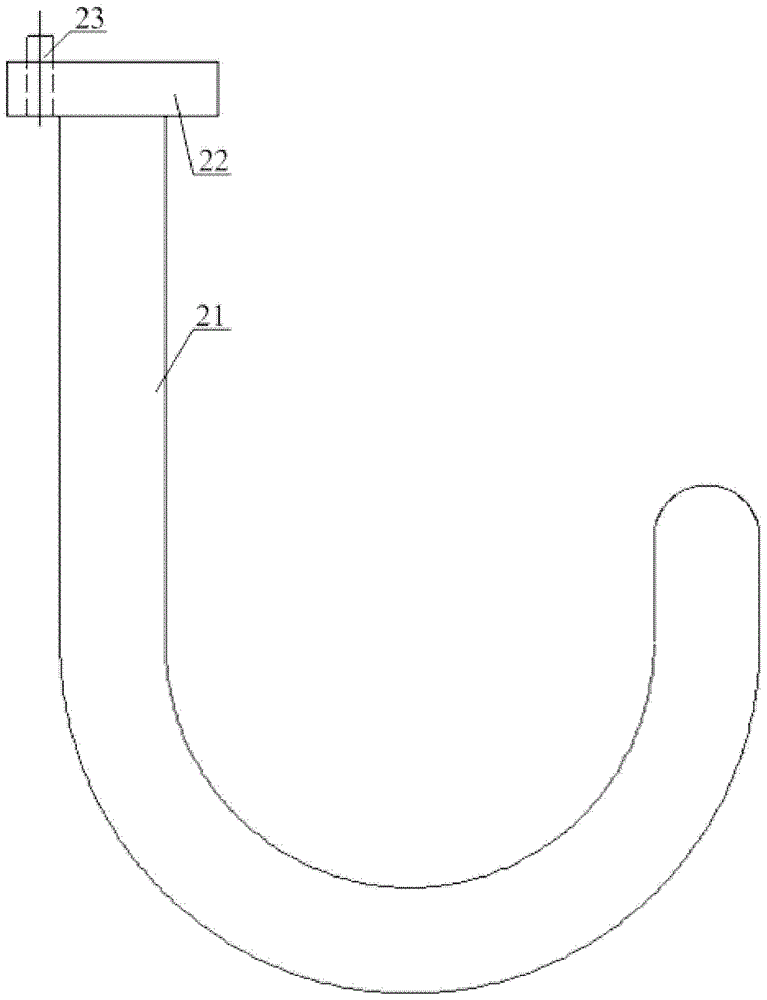
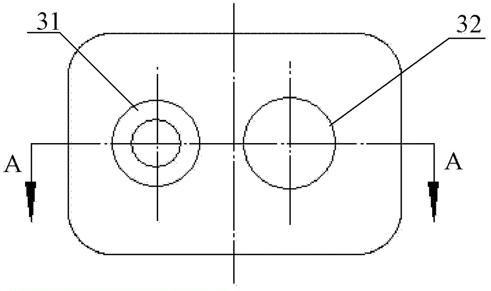
[0032] Such as figure 1 As shown, in Embodiment 1, the limit hook device of the present invention includes a circuit cover plate 1 and a hook 2, the hook 2 includes a hook body 21 and a hook top plate 22, the hook top plate 22 is arranged at one end of the hook body 21, and the hook The top plate 22 is provided with a limiting part for limiting the rotation angle of the hook. The hook 2 is installed on the circuit cover 1 through the hook stopper 3. The hook stopper 3 has a cavity matching the hook body 21. The circuit cover 1 There is a cavity that matches the top plate 22 of the hook, so that the hook 2 can rotate freely relative to the circuit cover 1, and the matching limit part of the circuit cover 1 is provided with an arc-shaped groove with an angle, so that the hook 2 is relatively opposite to the circuit cover. 1 limit rotation.

[0033] The first groove 11, the second groove 12, and the third groove 13 are successively provided on the circuit cover plate 1, and the...


PUM


Abstract

The invention discloses a limiting hook device which comprises a loop cover plate and a hook, wherein the hook comprises a hook body and a hook ejection plate; the hook ejection plate is arranged at one end of the hook body; a limiting part used for limiting the rotating angle of the hook is arranged on the hook ejection plate; the hook is mounted on the loop cover plate through a hook stop block; a cavity matched with the hook body is formed in the hook stop block; a cavity matched with the hook ejection plate is formed in the loop cover plate, so that the hook can freely rotate relative to the loop cover plate; and the loop cover plate is provided with an arc-shaped angular groove matched with the limiting part, so that the hook can be subjected to limited rotation relative to the loop cover plate. The limiting hook has the advantages of simple structure, capability of effectively limiting the rotating angle, low manufacturing cost, simple process and convenience for mounting and use.

Description

technical field [0001] The invention relates to a hook, in particular to a hook device with a position limiting function. Background technique [0002] The absorption circuit of the anesthesia machine is a combined gas circuit device connected between the anesthesia machine and the patient, and delivers anesthesia mixed gas to the patient. During the use of the anesthesia machine, due to the complexity of the anesthesia machine itself and the instrument lines and pipelines used in conjunction with it, if it is left to be placed randomly, it will bring a lot of inconvenience to the operator. In order to avoid the random placement of the lines and pipelines, it is necessary to The machine is equipped with a hook device for hanging lines and pipelines, which makes the operator's operating space tidy and convenient. [0003] Chinese patent document CN 201977511U discloses a "two-stage hook", such as Figure 8 As shown, the main body is the hook head 10, which is integrally conn...

Claims


Application Information

Patent Timeline
Patent Type & Authority Patents(China)
IPC IPC(8): F16L3/02
Inventor 张凯
Owner BEIJING AEONMED
Learn More