
Measurement method of pulse signal arrival time difference

A pulse signal and measurement method technology, applied in the field of signal parameter estimation, can solve the problems of large TDOA estimation error, large TOA measurement error, double threshold detection, etc., achieve high-precision estimation, overcome inherent bias, and reduce the effect of estimation variance

Active Publication Date: 2013-06-19
TSINGHUA UNIV
View PDF3 Cites 20 Cited by
  • Summary
  • Abstract
  • Description
  • Claims
  • Application Information

AI Technical Summary

Problems solved by technology

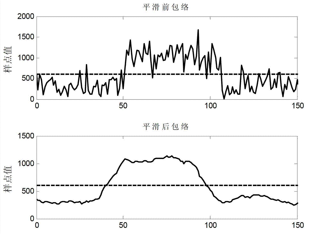
However, the actual received pulse signal of the radiation source is bound to be interfered by noise, especially under the condition of low SNR, the direct envelope detection method often introduces a large TOA measurement error, which leads to a relatively large TDOA estimation error between observation points. Big
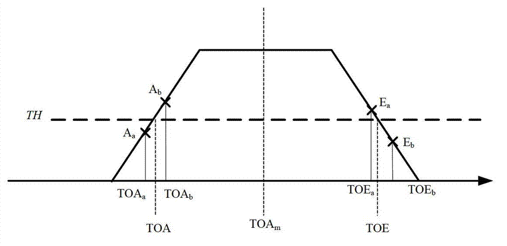
In addition, due to the directional characteristics of the antenna beam of the radiation source and the distance between the observation points, there is a certain difference in the pulse amplitude arriving at each observation point, and the fixed threshold detection method will lead to an inherent bias in the TDOA estimation
In order to overcome this problem, the existing methods mainly adopt the adaptive threshold method, which adjusts the threshold according to the pulse amplitude, but this method faces the problem of double threshold detection, and needs to perform initial detection and measure the pulse amplitude, which is more complicated to implement.

Method used


Image

  • Measurement method of pulse signal arrival time difference
  • Measurement method of pulse signal arrival time difference
  • Measurement method of pulse signal arrival time difference

Examples


Embodiment Construction

[0017] Embodiments of the present invention are described in detail below, examples of which are shown in the drawings, wherein the same or similar reference numerals designate the same or similar elements or elements having the same or similar functions throughout. The embodiments described below by referring to the figures are exemplary and are intended to explain the present invention and should not be construed as limiting the present invention.

[0018] In describing the present invention, it should be understood that the terms "center", "longitudinal", "transverse", "length", "width", "thickness", "upper", "lower", "front", " Orientation or position indicated by "back", "left", "right", "vertical", "horizontal", "top", "bottom", "inner", "outer", "clockwise", "counterclockwise", etc. The relationship is based on the orientation or positional relationship shown in the drawings, and is only for the convenience of describing the present invention and simplifying the descrip...


PUM


Abstract

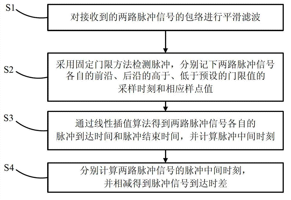
The invention provides a measurement method of pulse signal arrival time difference. The measurement method comprises the following steps: smoothly filtering envelope of a first pulse signal and a second pulse signal which are received; detecting pulses through a fixed threshold method, and respectively recording sampling time and corresponding sampling point values, higher and lower than preset threshold values, of leading edges and lagging edges of the first pulse signal and the second pulse signal; obtaining pulse arrival time and pulse finishing time of the first pulse signal and the second pulse signal through a linear interpolation algorithm; and respectively calculating pulse intermediate time of the first pulse signal and pulse intermediate time of the second pulse signal, and subtracting the pulse intermediate time of the first pulse signal from the pulse intermediate time of the second pulse signal to obtain the pulse signal arrival time difference. According to the measurement method, inherent deviation can be overcome effectively, estimation variance is one half of that of a traditional method, and time difference measurement performance can be improved obviously.

Description

technical field [0001] The invention relates to the technical field of signal parameter estimation, in particular to a method for measuring the time difference of arrival of pulse signals. Background technique [0002] Passive positioning technology refers to the emerging positioning technology that passively receives the radiation signal of the target radiation source to determine its position, and the time difference of arrival (TDOA, Time difference of arrival) between the observation points is the key to determine the spatial geometric position of the target radiation source. One of the main parameters. Pulse signals are widely used in communication, navigation, and radar, and their time difference of arrival measurement has become an important determinant for passive positioning of such radiation source targets. [0003] The time difference of arrival of the pulse signal refers to the time of arrival (TOA, Time of arrival) difference between the two observation points....

Claims


Application Information

Patent Timeline
Patent Type & Authority Applications(China)
IPC IPC(8): G01R29/02
Inventor 黄振陆建华肖心龙李振强郭智炜赵波
Owner TSINGHUA UNIV
Learn More