
Negative-pressure fan

A negative pressure fan and air inlet technology, applied in mechanical equipment, machines/engines, liquid fuel engines, etc., can solve the problems of time-consuming, dangerous negative pressure fans, labor-intensive efficiency, etc., to reduce loading and unloading risks, ensure loading and unloading accuracy, and improve The effect of loading and unloading efficiency

Inactive Publication Date: 2013-05-15
昆山俊润通风降温设备有限公司
View PDF6 Cites 2 Cited by
  • Summary
  • Abstract
  • Description
  • Claims
  • Application Information

AI Technical Summary

Problems solved by technology

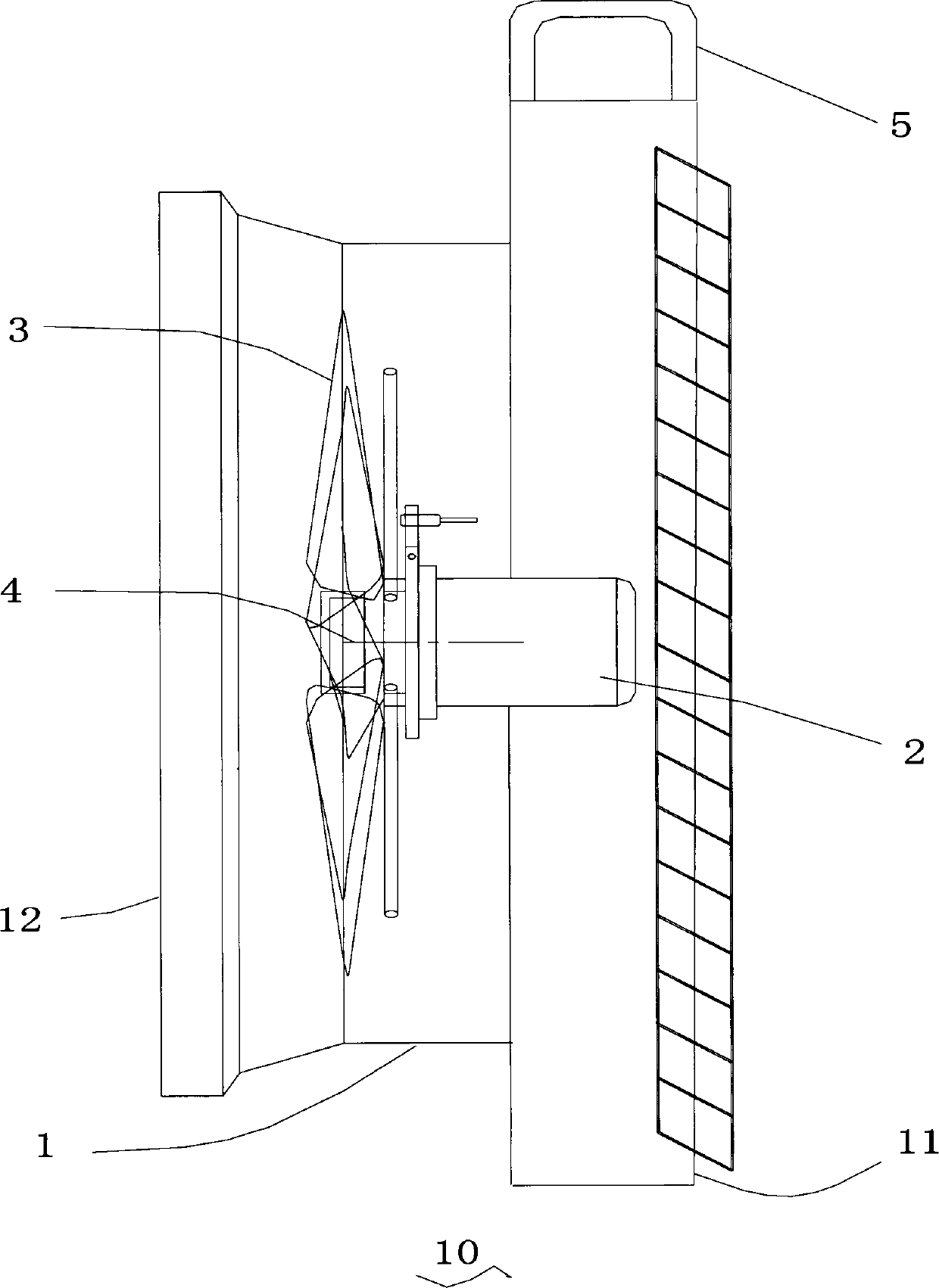
[0005] The object of the present invention is to provide a negative pressure fan with a loading and unloading handle to solve the problems of danger, time-consuming, laborious and inefficient transportation and loading and unloading of the negative pressure fan

Method used


Image

  • Negative-pressure fan
  • Negative-pressure fan

Examples


Embodiment Construction

[0015] The present invention will be described in detail below in conjunction with the implementations shown in the drawings, but it should be noted that these implementations are not limitations of the present invention, and those of ordinary skill in the art based on the functions, methods, or structural changes made by these implementations Equivalent transformations or substitutions all fall within the protection scope of the present invention.

[0016] refer to figure 2 as shown, figure 2 It is a cross-sectional view of a specific embodiment of the negative pressure machine 10 of the present invention. The negative pressure fan 10 of the present invention includes: a casing 1 , a motor 2 , fan blades 3 , a transmission shaft 4 and a loading and unloading handle 5 . The motor 2 and the fan blade 3 are respectively located in the square air inlet 11 and the circular air outlet 12 at both ends of the housing 1 , and are connected through the transmission shaft 4 . When t...


PUM


Abstract

The invention provides a negative-pressure fan. The negative-pressure fan comprises an outer shell, a motor, fan blades and a transmission shaft, wherein the motor and the fan blades are respectively arranged at two ends in the outer shell and are connected through the transmission shaft. The fan blades are driven to rotate by the motor through the transmission shaft, and an effect of negative-pressure air exchange is achieved. Handles for loading and unloading are arranged on the outer shell. When the negative-pressure fan is moved, loaded and unloaded by workers, the negative-pressure fan can be lifted or lowered to the appointed height through the handles for loading and unloading to be operated, so that man-made damage risks of the negative-pressure fan in a process of moving, loading and unloading are reduced, a security coefficient of workers in a process of loading and unloading is improved, efficiency of loading and unloading is improved, and installation accuracy is guaranteed.

Description

technical field [0001] The invention relates to a negative pressure fan, in particular to a negative pressure fan with a loading and unloading handle. Background technique [0002] Negative pressure fans use the principle of air convection and negative pressure ventilation to naturally inhale fresh air from the opposite side of the installation site --- the door or window, and at the same time quickly force the indoor stuffy air out of the room to achieve cooling and cooling effects. kind of machine. Because of its low investment cost (the one-time investment is only one-sixth of the air conditioner), large air volume (the air change rate can reach 99%), low noise, and low energy consumption (the operating cost is only one-tenth of the air conditioner) , stable operation, long life and high efficiency, so it has been used by more and more industrial and mining plants, and it is also a good choice for cooling and ventilation in modern workshops. In particular, safe, environ...

Claims


Application Information

Patent Timeline
Patent Type & Authority Applications(China)
IPC IPC(8): F04D25/08F04D29/52
Inventor 吕学兵
Owner 昆山俊润通风降温设备有限公司
Learn More