Fast ignition target fuel layering device based on fluid magnetic suspension and fast ignition target fuel layering method based on fluid magnetic suspension

A fuel stratification and magnetic levitation technology, applied in the field of inertial confinement nuclear fusion, can solve the problems of limited use range, low fuel filling amount, and ineffectiveness, and achieve the effect of expanding the use range, convenient operation and reliable operation.

Inactive Publication Date: 2013-05-08
XI AN JIAOTONG UNIV
View PDF4 Cites 14 Cited by
  • Summary
  • Abstract
  • Description
  • Claims
  • Application Information

AI Technical Summary

Problems solved by technology

Among the three target types, only the structure of the fast-ignition target is non-spherically symmetrical, so traditional layering techniques such as β-layering and infrared-assisted layering are difficult to work on it
The radius of each micropore in the foam material should be as large as possible to avoid interference with fuel ignition, which limits the adsorption capacity and strength of the foam material
Therefore, when performing fuel stratification on a fast-ignition target with a large diameter

Method used


Image

  • Fast ignition target fuel layering device based on fluid magnetic suspension and fast ignition target fuel layering method based on fluid magnetic suspension
  • Fast ignition target fuel layering device based on fluid magnetic suspension and fast ignition target fuel layering method based on fluid magnetic suspension
  • Fast ignition target fuel layering device based on fluid magnetic suspension and fast ignition target fuel layering method based on fluid magnetic suspension

Examples


Embodiment Construction

[0027] The present invention will be described in further detail below in conjunction with the accompanying drawings.

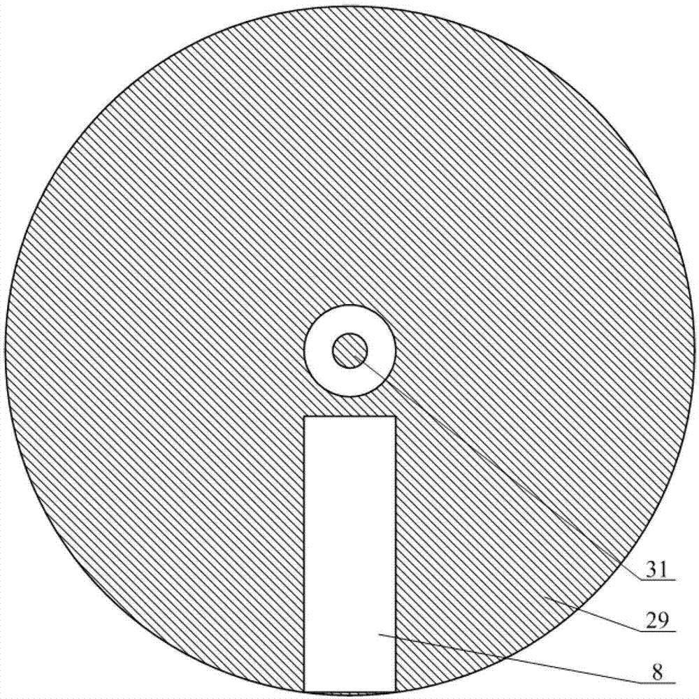
[0028] refer to figure 1, a fast ignition target fuel stratification device based on fluid magnetic levitation, including a turntable mechanism 1, the turntable mechanism 1 is composed of a drive shaft 31, a turntable 29 and a target chamber 8, the drive shaft 31 is parallel to the ground, and the turntable 29 is fixed on the drive shaft 31, the disk surface of the rotating disk 29 is perpendicular to the central axis of the drive shaft 31, and the driving shaft 31 can be used to rotate the rotating disk 29 counterclockwise in the vertical plane. The disk surface of the rotating disk 29 is grooved radially, and the target chamber 8 is installed. Target making room 8 profile is cube, and its cross section is square, and the symmetry axis of its longitudinal section is along the radial direction of rotating disk 29; When the target chamber 8 is in the vertical...


PUM


Abstract

The invention discloses a fast ignition target fuel layering device based on fluid magnetic suspension and a fast ignition target fuel layering method based on the fluid magnetic suspension. The fast ignition target fuel layering device based on the fluid magnetic suspension comprises a turnplate mechanism which is composed of a drive shaft, a turnplate and a target making chamber. The turnplate is fixed on the drive shaft, a groove is formed in the plate face of the turnplate along the radial direction, the target making chamber is installed, a guide rail is fixed in the target making chamber, a heat exchanger and a target seat are placed on the two sides of a slide block, an anti-radiation shield is fixed on the target seat, one end of a clamping arm is fixed to the slide block, the other end of the clamping arm is connected with a supporting rod which is bonded to a gold cone shell of a target pellet, a hydrogen filing tube is communicated with a capillary tube and a liquid hydrogen container, and the hydrogen filling tube is also communicated with the anti-radiation shield and a gas hydrogen container. When fuel is layered, the slide block is located at the tail end of the guide rail, and the layering method includes that the fluid magnetic suspension technology is adopted to basically counteract the gravity force of liquid fuel, the strength of foamed material is enabled not to be a restraining factor for fuel layering, and therefore the requirements for fast ignition target fuel layering of large-diameter thick material layers are met. The fast ignition target fuel layering device based on the fluid magnetic suspension and the fast ignition target fuel layering method based on the fluid magnetic suspension have the advantages of being simple in structure, reliable in operation, and convenient to operate.

Description

technical field [0001] The invention relates to the technical field of inertial confinement nuclear fusion, in particular to a fast-ignition target fuel stratification device and method based on fluid magnetic levitation. Background technique [0002] Fluid magnetic levitation technology means that by applying an external magnetic field, the magnetic field force and gravity are basically offset on each particle of the target fluid, and then the weak molecular cohesion in the fluid is used to make the fluid microgroup achieve a suspension effect. The magnetic acceleration generated by the artificial magnetic field generally changes with the spatial position, while the gravitational acceleration can be regarded as uniform in space, so the magnetic field force cannot completely offset the gravity at each particle point of the object, and it needs to be realized through the joint action of the magnetic field force, gravity, and molecular cohesion. Maglev. The molecular cohesion...

Claims


Application Information

Patent Timeline
IPC IPC(8): G21B1/03
CPCY02E30/14Y02E30/10
Inventor 厉彦忠郑江
Owner XI AN JIAOTONG UNIV
Why Eureka
Try Eureka