
Underwater silt remover, underwater silt removing device comprising the same and operation method thereof

A technology of underwater dredging machine and submersible motor, which is applied in the direction of earth mover/shovel, mechanically driven excavator/dredger, construction, etc., can solve the problem of high production cost and complex structure of underwater dredging machine. question

Active Publication Date: 2015-05-20
枣庄高新区立正建筑工程有限公司
View PDF7 Cites 1 Cited by
  • Summary
  • Abstract
  • Description
  • Claims
  • Application Information

AI Technical Summary

Problems solved by technology

[0007] This underwater dredger has complex structure and high manufacturing cost

Method used


Image

  • Underwater silt remover, underwater silt removing device comprising the same and operation method thereof
  • Underwater silt remover, underwater silt removing device comprising the same and operation method thereof
  • Underwater silt remover, underwater silt removing device comprising the same and operation method thereof

Examples


no. 1 example

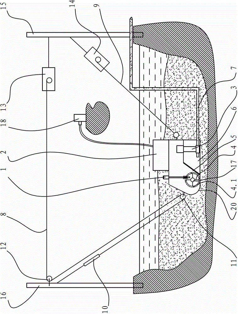
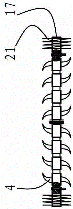
[0090] see Figure 1-Figure 2 , the underwater desilting machine, including the collecting bin 6 arranged in the frame 20, the inlet of the mud pump 3 communicates with the collecting bin 6, the outlet of the mud pump 3 communicates with the mud outlet pipe 7, and the frame 20 is also provided with Disturbance stirring mechanism, this disturbance stirring mechanism comprises the rotary tiller blade 4 with ridging function and the submersible motor 1 and the speed reducer for driving the rotary tiller blade 4 to rotate, and the filter screen 5 is arranged on the collecting bin 6, and the rotary tiller blade 4 is located at The front of the filter screen 5 and the collection bin 6.

[0091] The submersible motor 1 is suspended on the frame 20, and the submersible motor 1 is connected to the rotating shaft 17 arranged in the frame 20 through a reducer, and more than two rotary blades 4 are relatively symmetrically arranged on the rotating shaft 17; the rotating shaft 17 The two ...

no. 2 example

[0153] see Figure 5 , In the present embodiment, the submersible motor 1 is located at the oblique rear top of the rotary blade 4 . At this time, the submersible motor 1 is arranged horizontally, and the sealing level requirement of the submersible motor 1 is slightly higher than that of the first embodiment.

[0154] Refer to the first embodiment for the rest of the undescribed parts, and will not repeat them here.

no. 3 example

[0156] see Figure 6 , In this embodiment, the submersible motor 1 is installed obliquely, and the submersible motor 1 is located at the oblique front and top of the rotary blade 4 . The front part or the front lower half of the frame 20 is pointed, which can reduce the resistance of advancement and prevent subsidence. Refer to the first embodiment for the rest of the undescribed parts, and will not repeat them here.


PUM


Abstract

Provided are an underwater silt remover, an underwater silt removing device comprising the same and an operation method thereof. The underwater silt remover comprises a collecting bin arranged in a machine frame, an inlet of a sludge pump is communicated with the collecting bin, an outlet of the sludge pump is communicated with a sludge outlet pipe, a stirring blending mechanism is further arranged in the machine frame, the stirring blending mechanism comprises a rotary blade with a ridging function and a diving motor used for driving the rotary blade to rotate, a filtering net is arranged on the collecting bin, and the rotary blade is located in the front of the collecting bin. Power for driving the underwater silt remover to move forwards in sludge is from traction force of a first winch. The traction force is output to the first elastic balancer, a spring of the first elastic balancer is stretched to perform conversion storage of energy, then in the process of silt removing work of the underwater silt remover, the spring of the first elastic balancer slowly retracts to the original shape, releases stored energy, and supplies the power to the underwater silt remover for moving forwards.

Description

technical field [0001] The invention relates to an underwater dredging machine, in particular to an underwater dredging machine, underwater dredging equipment including the underwater dredging machine and an operating method thereof. Background technique [0002] Existing dredging machines, dredging boats or dredging pumps are seldom used in production because they are bulky, expensive, inconvenient to operate, difficult to move and install, and unreasonable in design. [0003] At present, the bottom of most ponds is deposited with silt, which occupies a large amount of water space in the pond, causing the water body to become shallower, smaller, and turbid, thereby affecting the photosynthesis of aquatic algae in the pond. In addition, due to the silt in the pond The decomposition of rich organic matter releases ammonia nitrogen, methane, carbon dioxide, hydrogen sulfide and other harmful substances to poison the water body, breed harmful parasites, viruses, bacteria and ot...

Claims


Application Information

Patent Timeline
Patent Type & Authority Patents(China)
IPC IPC(8): E02F5/28E02F5/30E02F3/88E02F3/90
Inventor 梁华安
Owner 枣庄高新区立正建筑工程有限公司
Learn More