
Electromagnetic relay with armature part convenient to insert

A technology of electromagnetic relays and armatures, which is applied in the direction of electromagnetic relays, electromagnetic relay details, relays, etc., can solve the problems of high difficulty, unfixed position of armature parts, and difficulties in automatic assembly, so as to reduce assembly difficulty and improve assembly efficiency. Effect

Active Publication Date: 2015-03-11
XIAMEN HONGFA ELECTROACOUSTIC CO LTD
View PDF4 Cites 0 Cited by
  • Summary
  • Abstract
  • Description
  • Claims
  • Application Information

AI Technical Summary

Problems solved by technology

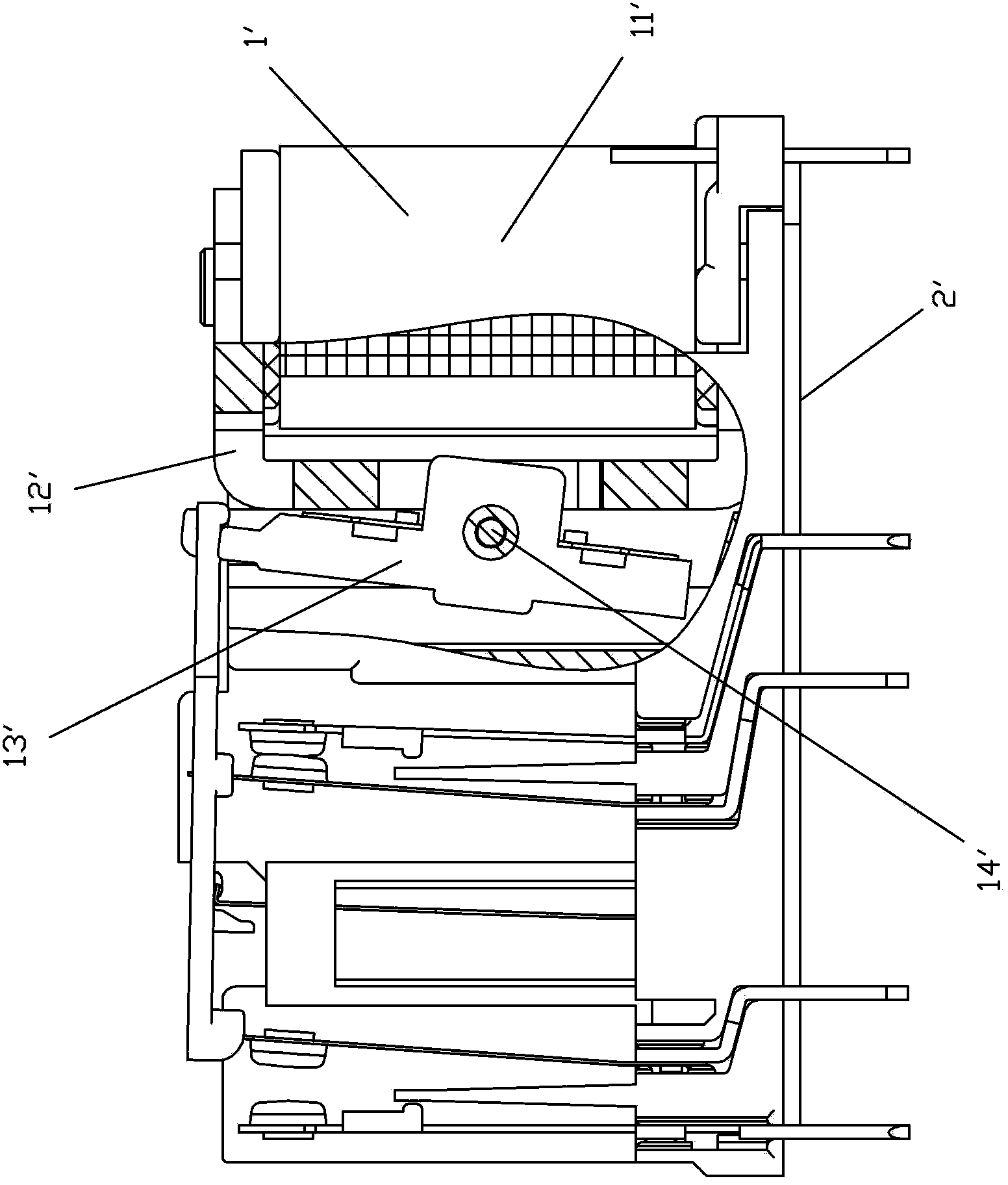
[0003] This structure has the following disadvantages: when the rotating shaft 14' is not inserted, although the yoke 12' and the coil 11' of the magnetic circuit part can be fixed together after being inserted into each other, the armature part 13' and other parts of the magnetic circuit part There is no fixed connection between the components, that is, the position of the armature part is not fixed when the rotating shaft 14' is not inserted, which brings great difficulties to assembly, especially automatic assembly, because the position of the armature part 13' is not fixed. In the process of installing the magnetic circuit part into the base as a whole, the rotating shaft 14' must first pass through the shaft hole on one side of the base 2', and then be accurately inserted into the shaft hole of the armature part 13', and then accurately It is very difficult to pass through the shaft hole on the other side of the base 2', and it is impossible to realize automatic assembly at all.

Method used


Image

  • Electromagnetic relay with armature part convenient to insert
  • Electromagnetic relay with armature part convenient to insert
  • Electromagnetic relay with armature part convenient to insert

Examples


Embodiment Construction

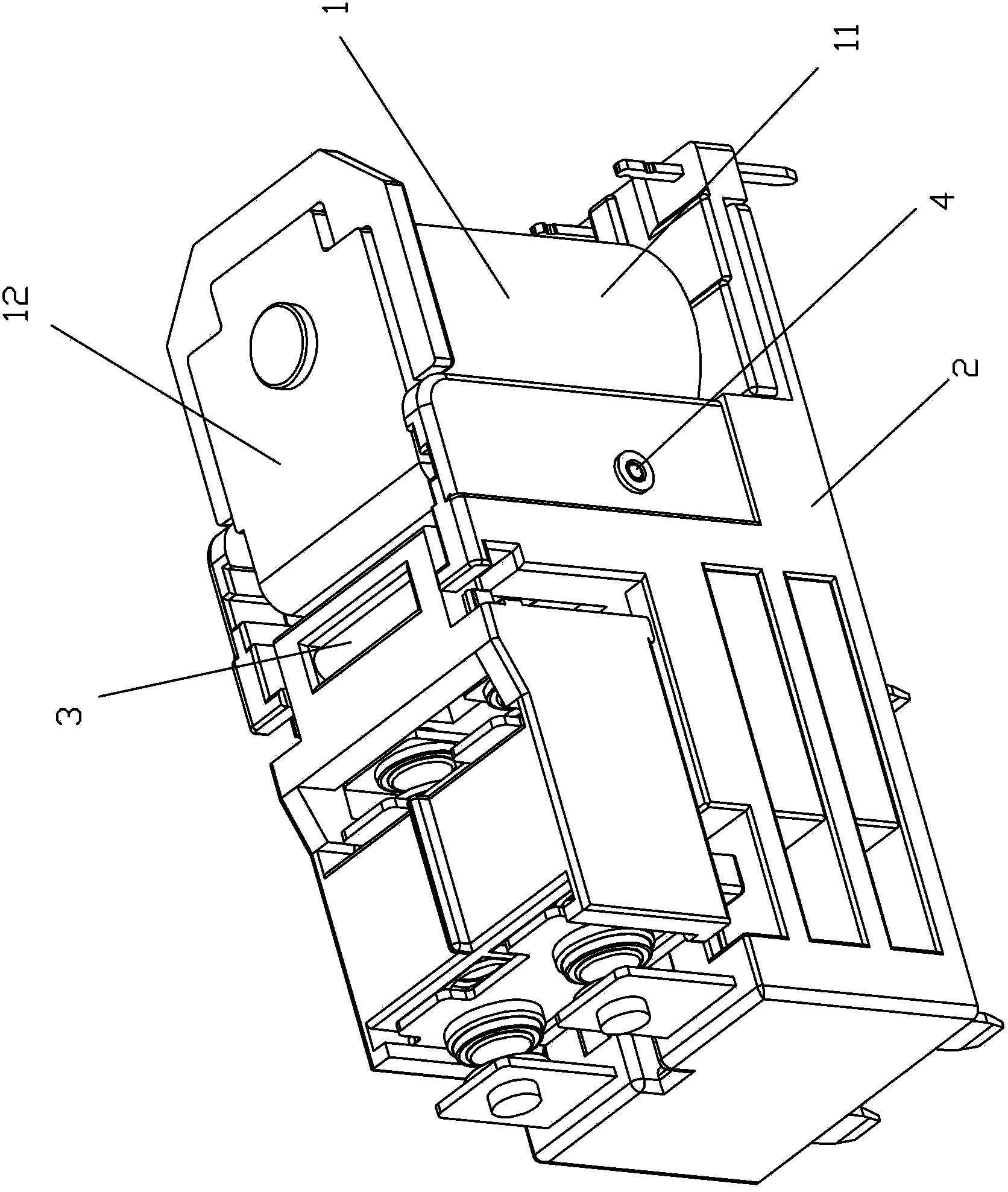
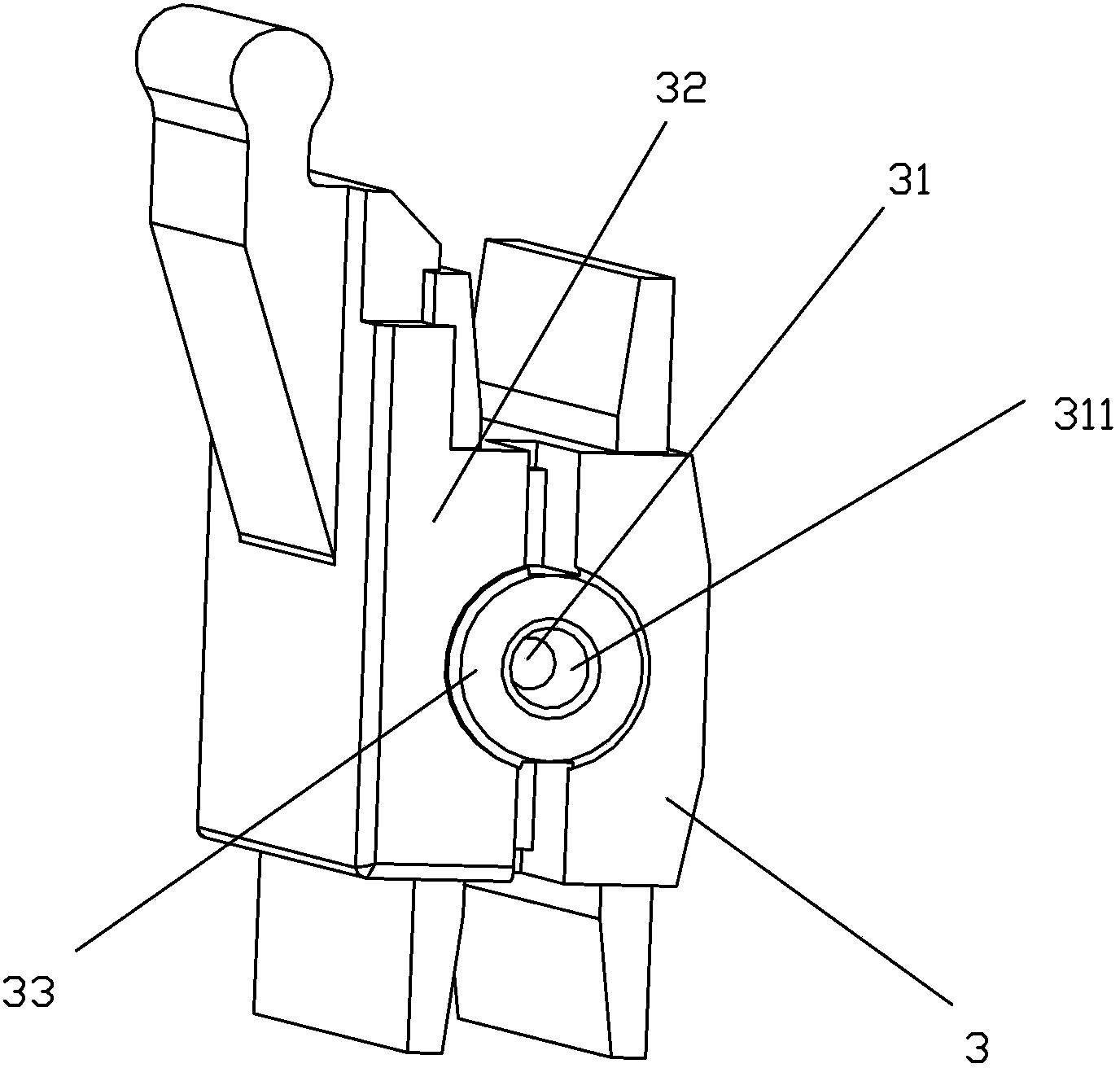
[0029] Examples, see Figure 2 to Figure 11 As shown, an electromagnetic relay of the present invention that is convenient for inserting an armature part includes a magnetic circuit part 1 and a base 2; the magnetic circuit part 1 is installed on the base 2; the magnetic circuit part 1 includes an armature part 3, a coil 11 and a yoke 12, wherein the armature part 3 is installed on the base 2 through a rotating shaft 4; the armature part 3 is provided with a first shaft hole 31 adapted to the rotating shaft, and the first shaft hole 31 penetrates two opposite sides of the armature part The side surface 32; the base 2 is provided with two opposite support parts 21, and the two support parts 21 are respectively provided with a second shaft hole 211 adapted to the rotating shaft; the armature part 3 is fitted between the two support parts 21 of the base , and is positioned on the base 2 through the cooperation of the rotating shaft 4 with the first shaft hole 31 and the second sh...


PUM


Abstract

The invention discloses an electromagnetic relay with an armature part convenient to insert. The electromagnetic relay comprises a magnetic circuit part and a base. The magnetic circuit part comprises the armature part which is installed on the base through a rotary shaft. The armature part is provided with a first shaft hole. The base is provided with two supporting parts which are provided with second shaft holes. The armature part is matched between the two supporting parts and positioned on the base through match of the first and second shaft holes. Protruding bumps respectively extend outward on two side face of the armature part. Brackets are respectively arranged on the inner side surfaces opposite to the two supporting parts of the base. The rotary shaft is installed into the first and second shaft holes through match of the protruding bumps and the brackets. According to the structure, the rotary shaft in the armature part can be easily threaded to the shaft holes of the armature part through the shaft hole of the base, so that the armature part is positioned on the shaft hole of the base by means of the central rotary shaft, so as to assemble the armature part automatically. Meanwhile, the armature part can be further prevented from being abraded with the base when the armature part rotates around the rotary shaft.

Description

technical field [0001] The invention relates to an electromagnetic relay, in particular to an electromagnetic relay which is convenient for inserting armature parts and is suitable for automatic assembly. Background technique [0002] An existing electromagnetic relay, such as figure 1 As shown, it usually includes a magnetic circuit part 1' and a base 2', the magnetic circuit part 1' is installed on the base 2', and the magnetic circuit part 1' usually includes a coil 11', a yoke 12' and an armature part 13' When assembling, the magnetic circuit part 1' is installed into the base 2' together as a whole, positioned on the positioning groove of the base 2' by the yoke 12', and then inserted into the rotating shaft 14', so that the armature part 13' can rely on its center The rotating shaft 14' is positioned to rotate on the shaft hole of the base 2'. [0003] This structure has the following disadvantages: when the rotating shaft 14' is not inserted, although the yoke 12' a...

Claims


Application Information

Patent Timeline
Patent Type & Authority Patents(China)
IPC IPC(8): H01H50/18
Inventor 蔡文智谭忠华刘金枪王其亚
Owner XIAMEN HONGFA ELECTROACOUSTIC CO LTD
Learn More