
Deep tillage rotary plow

A technology of plow and rotary plow, applied in the field of deep-plow rotary plow, can solve problems affecting crop yield, soil degradation, and affecting the emergence rate of crop winter wheat, so as to facilitate germination and root growth, increase soil nitrogen content, and realize food production. The effect of increasing production

Inactive Publication Date: 2015-11-18
邯郸市远华气力输送科技股份有限公司
View PDF5 Cites 0 Cited by
  • Summary
  • Abstract
  • Description
  • Claims
  • Application Information

AI Technical Summary

Problems solved by technology

[0002] Because the rotary tillage plow has the advantages of flat land, no rubbish, and fast farming speed, it is very popular among farmers; but because the common rotary tillage knife is 160 cm long, with a 90° straight bend, and is made of high carbon steel, the rotary tiller can be used during work. The action similar to "hoeing" makes the soil cultivation layer shallower by 10-15 cm; in addition, the ordinary rotary tiller gearbox is a three-stage variable speed, the output speed is 300 rpm, the gear module is 6, and the speed ratio is large, resulting in continuous work. When the temperature is too high, it needs to be shut down for cooling; therefore, after returning the straw to the field, the commercially available rotary plows distribute a large amount of straw on the soil surface, which affects the emergence rate of crops such as winter wheat, often resulting in difficult rooting of crops, lodging, pests and diseases. ; Due to the shallow plowing layer, repeated plowing and rolling should form repeated soil compaction, resulting in a decrease in soil organic matter content, insufficient fertility absorption, soil water seepage, reduced water storage capacity, increased surface runoff, and aggravated the process of soil erosion. The return rate is low and cannot supplement the nutrients needed for crop growth, eventually leading to soil degradation and affecting crop yields

Method used


Image

  • Deep tillage rotary plow
  • Deep tillage rotary plow
  • Deep tillage rotary plow

Examples


Embodiment Construction

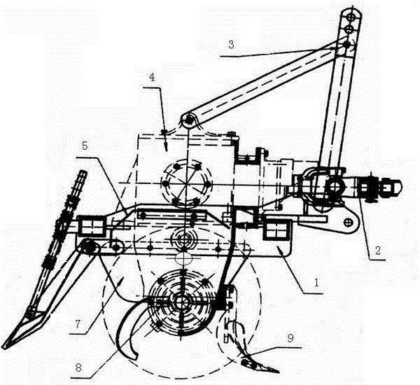
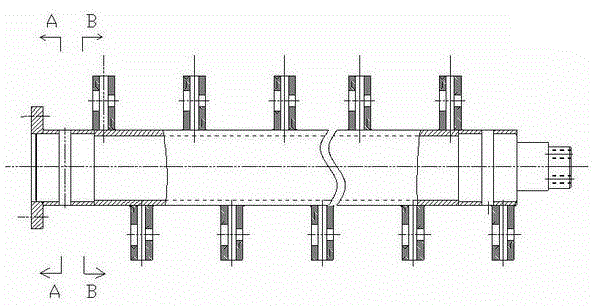
[0016] As shown in the figure, the deep-plow rotary plow consists of a frame assembly 1, a universal joint assembly 2, a suspension frame assembly 3, a gearbox assembly 4, a cutter shaft assembly 8, a machine cover 5, a side plate 7 and The rotary tiller is composed of 9; the middle part of the frame assembly 1 is provided with a gearbox assembly 4; the gearbox assembly 4 is connected with the output shaft at the tail of the tractor through the universal joint assembly 2; the output shaft of the gearbox assembly 4 Drive the cutter shaft assembly 8 to rotate; the rotary tiller blade mounting seat is provided on the cutter shaft assembly 8, and the rotary tiller blade 9 is installed on the cutter shaft assembly 8 through the rotary blade mounting seat; the rotary tiller blade 9 is Deep tillage rotary tiller.

[0017] The deep-plow rotary plow is characterized in that: the deep-plow rotary plow is composed of a handle 9-1, a blade body 9-2 and a cutter head 9-4; wherein the handl...


PUM


Abstract

The invention relates to a deep ploughing rotary plow which consists of a frame assembly (1), a universal joint assembly (2), a suspension frame assembly (3), a transmission box assembly (4), a cutter shaft assembly (8), a hood (5), a side plate (7), and a rotary blade (9). The transmission box assembly (4) is arranged in the middle of the frame assembly (1). The transmission box assembly (4) is connected with the output shaft on the tail part of a tractor through the universal joint assembly (2). The output shaft of the transmission box assembly (4) drives the cutter shaft assembly (8) to rotate. The cutter shaft assembly (8) is provided with a rotary blade installation seat. The rotary blade (9) is installed on the cutter shaft assembly (8) through the rotary blade installation seat. The rotary blade (9) is a deep ploughing rotary blade. The rotary plowed soil not only reaches the international requirement of more than 25cm in depth, but also excesses current agricultural depth: 16-22cm greatly. According to the deep ploughed land by means of the technical means, the average depth of the plough layer is 28-35cm, and maximally 40cm.

Description

technical field [0001] The invention relates to an agricultural implement, in particular to a deep-plow rotary plow. Background technique [0002] Because the rotary tillage plow has the advantages of flat land, no rubbish, and fast farming speed, it is very popular among farmers; but because the common rotary tillage knife is 160 cm long, with a 90° straight bend, and is made of high carbon steel, the rotary tiller can be used during work. The action similar to "hoeing" makes the soil cultivation layer shallower by 10-15 cm; in addition, the ordinary rotary tiller gearbox is a three-stage variable speed, the output speed is 300 rpm, the gear module is 6, and the speed ratio is large, resulting in continuous work. When the temperature is too high, it needs to be shut down for cooling; therefore, after returning the straw to the field, the commercially available rotary plows distribute a large amount of straw on the soil surface, which affects the emergence rate of crops such...

Claims


Application Information

Patent Timeline
Patent Type & Authority Patents(China)
IPC IPC(8): A01B33/02A01B33/10
Inventor 刘华民
Owner 邯郸市远华气力输送科技股份有限公司
Learn More