
Wire-harness protection structure

A technology for protecting structures and components, applied in the direction of circuits or fluid pipelines, insulated conductors, cables, etc., can solve the problems of increased workload and increased number of parts, and achieve the effect of easy operation and management

Inactive Publication Date: 2013-03-27
YAZAKI CORP
View PDF4 Cites 4 Cited by
  • Summary
  • Abstract
  • Description
  • Claims
  • Application Information

AI Technical Summary

Problems solved by technology

In this case, when the bellows 500 is divided into a plurality of parts respectively for the interference part 503, then the number of parts increases or the workload increases

Method used


Image

  • Wire-harness protection structure
  • Wire-harness protection structure
  • Wire-harness protection structure

Examples


Embodiment Construction

[0037] Exemplary embodiments of the present invention are now described by referring to the accompanying drawings.

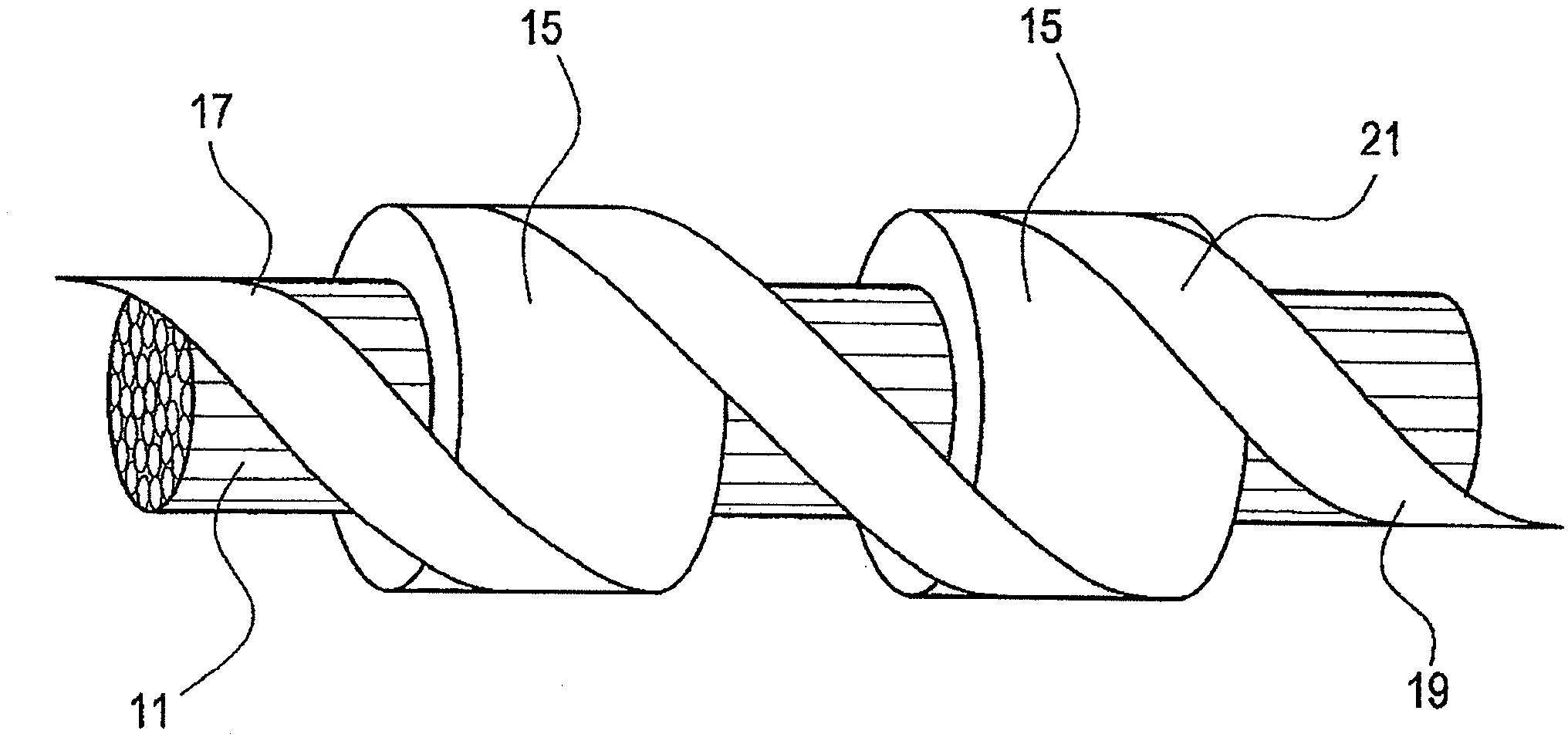
[0038] figure 1 is a perspective view of the appearance of the wire harness protective structure according to the first exemplary embodiment of the present invention.

[0039] This wire harness protection structure serves to protect a predetermined portion of the wire harness 11 from interference by other members. The wire harness 11 may be a single wire or a bundle of multiple wires. This wire harness protection structure includes: a protection member 15 that covers the outer periphery in a predetermined portion of the wire harness 11 ; and an adhesive tape 21 for fixing that fixes the protection member 15 .

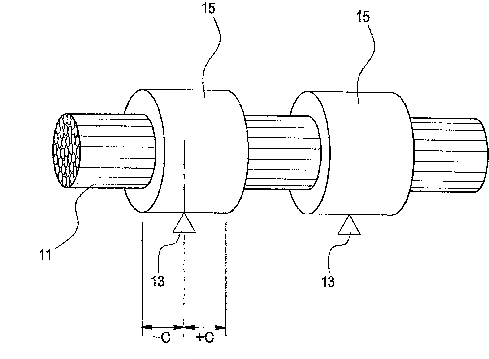
[0040] figure 2 is a perspective view of the wire harness before the adhesive tape for fixing is wound around the wire harness.

[0041] The wire harness protection structure may have a predetermined portion or predetermined portions to be protected...


PUM


Abstract

Provided is a wire-harness protection structure, wherein the amount and types of protection materials can be reduced, and the overall weight of a wire harness can be made to be lighter. The wire-harness protection structure, which protects prescribed portions of a wire harness (11) from interference by other members, is provided with: protection materials (15) that cover the outer circumference of the wire harness (11) at the prescribed portions; and a fixing adhesive tape (21) the starting end (17) of which is wound around the wire harness (11) and fixed thereto, which is wound around the outer circumference of the protection materials (15) to fix the protection materials (15) in place, and the terminal end (19) of which is wound around the wire harness (11) at the opposite side of the starting end (17) with respect to the protection materials (15), and fixed thereto.

Description

technical field [0001] The present invention relates to a wire harness protection structure that protects a predetermined portion of a wire harness from interference from other members. Background technique [0002] Since the wire harness is attached to the vehicle body, it is considered that the wire harness is in contact with peripheral members of the vehicle body laying passage, so that the outer sheath may be rubbed due to vibration. Therefore, corrugated tubes, tubes, and vinyl sheets are occasionally attached to the outer circumference of the wire harness for the purpose of protecting the wire harness (for example, see Patent Document 1). Such as Image 6 As shown in , the bellows 500 has a corrugated cylindrical shape and slits formed along its axial direction. In order to attach the corrugated tube 500 to the wire harness 501 , the slit is forcibly opened to cover the outer circumference of the wire harness 501 with the corrugated tube 500 . Then, both ends of the ...

Claims


Application Information

Patent Timeline
Patent Type & Authority Applications(China)
IPC IPC(8): H02G3/04B60R16/02H01B7/00
CPCH02G3/0462B60R16/02H01B7/00H02G3/0481H02G3/04B60R16/0215H02G3/0406
Inventor 渡边仁森重树
Owner YAZAKI CORP
Learn More